Description
GE DS200SDCCG1A Drive Control Card
Product Introduction
The GE DS200SDCCG1A is an SDCC Drive Control Card used in GE’s legacy Mark V control architecture. GE documentation identifies the G1A card group for AC2000, DC2000, and EX2000 drive applications, making this board relevant to both industrial drive-control equipment and excitation-related systems built around the Mark V platform. It is not a conventional PLC CPU or standalone communication module. The SDCC performs application-specific drive processing, I/O management, control calculations, and interface functions within the larger GE control system.
The processing architecture is one of the defining characteristics of the GE DS200SDCCG1A. The board incorporates three principal processors: a Drive Control Processor, a Motor Control Processor, and a Co-motor Processor used for more demanding mathematical processing. The processors share access to dual-ported memory, allowing different portions of the control workload to be handled without reducing the board to a single general-purpose CPU. The DCP handles drive-level functions and user-interface software, while the MCP provides high-speed analog/digital I/O and motor-control processing. The CMP is used when additional mathematical processing is required.
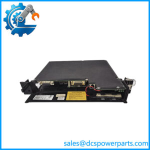
For maintenance teams, the GE DS200SDCCG1A should be treated as a system-specific control board rather than a commodity PCB. GE’s documentation describes configurable hardware jumpers, wire jumpers, onboard memory, diagnostic LEDs, and multiple connections to other control and interface boards. The board can interface with components such as the LAN Communications Card, Signal Processor Card, Multibridge Signal Processing Card, and drive terminal boards. Replacement therefore requires attention to firmware, configuration data, connector wiring, auxiliary boards, and the exact application—not simply physical fit.
Technical Specifications
| Parameter | Specification |
|---|---|
| Product Model | DS200SDCCG1A |
| Manufacturer | General Electric |
| Product Series | Mark V / DS200 |
| Functional Acronym | SDCC |
| Product Type | Drive Control Card |
| Primary Application Group | AC2000, DC2000, EX2000 |
| Processor Architecture | Three primary microprocessors |
| Drive Control Processor | 80C186-based |
| Motor Control Processor | 80C196-based |
| Co-motor Processor | TMS32002 signal processor |
| Memory Architecture | Dual-ported RAM / onboard EEPROM and EPROM memory |
| Analog I/O | Supported through SDCC interface circuitry |
| Digital I/O | Supported through SDCC interface circuitry |
| Main Connectors | 1PL, 2PL, 3PL, 6PL, 7PL, 8PL, 9PL, 11PL |
| Diagnostic Interface | 10 diagnostic LEDs |
| Configuration | Hardware jumpers, wire jumpers, software parameters |
| Instruction Manual | GEI-100029 |
| Communication | Via associated Mark V interface/LAN hardware as configured |
| Mounting | Mark V rack |
| PCB Coating | Normal coating |
| Hardware Group | G1 |
| Board Revision | A |
| PLC Protocol | Not a standalone PLC communication module |
| Operating Temperature | Verify against the applicable GEI-100029 installation requirements |
| Protection Rating | Board-level specification; verify enclosure/rack environmental conditions |
The processor and connector information above is based on GEI-100029 and corroborating technical documentation. Exact electrical supply, environmental limits, and I/O characteristics should not be inferred from generic DS200 listings because the SDCC is installed as part of a larger Mark V control assembly.
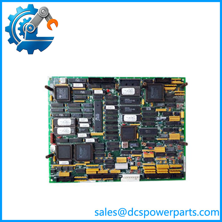
DS200SDCCG1A
Main Features and Engineering Considerations
Three-processor control architecture
The SDCC’s architecture separates drive control, motor-control processing, and additional mathematical processing. This is important when troubleshooting because a board fault does not necessarily present as a simple “CPU failure.” Processor-specific diagnostics, memory faults, I/O problems, and interface-board faults can produce different symptoms.
Application-specific G1A configuration
GE documentation distinguishes the SDCC groups by application. DS200SDCCG1A is the G1A group for AC2000, DC2000, and EX2000 applications, while G3A is associated with DC1000 and G4A with TC2000 applications. Therefore, an SDCC board should not be substituted merely because another card has the same SDCC designation.
Extensive board-to-board interfaces
The SDCC uses multiple connectors to communicate with other boards. Documented interfaces include connections to the power supply/interface board, LAN communications hardware, terminal boards, and signal-processing boards. A loose connector, incorrect cable position, or damaged mating board can therefore look like an SDCC processor fault during troubleshooting.
Diagnostic LED system
GE documentation specifies a bank of 10 diagnostic LEDs used to display fault information. These LEDs can provide useful information before removing the board or disturbing configuration hardware. Maintenance personnel should record the displayed diagnostic condition before power removal.
Memory and configuration considerations
The SDCC design uses four factory-programmed EPROMs and one EEPROM containing field-adjustable parameters. GE documentation specifically warns that the DS200SDCC board does not include these five memory chips when supplied as a bare board, and recommends the DS215SDCC replacement when those memory devices need to be included. This is a critical distinction when sourcing a replacement.
Auxiliary-board compatibility
The SDCC provides mounting provisions for auxiliary cards including the DS215SLCC/531X306LCC LAN Communications Card and signal-processing boards. The exact auxiliary-board combination should be checked against the original drive or excitation cabinet documentation before replacement.
Application Scenarios
- GE AC2000 drive systems
- GE DC2000 drive systems
- GE EX2000 excitation systems
- Mark V turbine-related control equipment
- Industrial motor-drive control
- Generator excitation control
- Legacy GE Speedtronic installations
- Drive terminal-board interfaces
- Signal-processing board interfaces
- Mark V control cabinet maintenance and spare replacement
Engineer’s Guide: Field Pitfalls
Do not classify as a generic PLC CPU. It is an application-specific SDCC Drive Control Card designed for the Mark V control architecture.
Do not assume Mark VI compatibility. The belongs to the Mark V DS200 family. Generic reseller descriptions sometimes incorrectly associate individual DS200 boards with Mark VI systems. The application and hardware family should be established from the original cabinet documentation.
Do not replace G1A with another SDCC group without engineering verification. GE identifies G1A, G3A, and G4A as different application groups.
Check the memory devices. A bare DS200SDCC board may have empty memory sockets. GE’s manual specifically highlights this issue and identifies DS215SDCC as the replacement approach when the five memory chips need to be included.
Record configuration before removal. Photograph jumper positions, wire jumpers, connector locations, board markings, and diagnostic LEDs before removing an installed card.
Check every mating board. SDCC faults can be caused by associated LAN, signal-processing, terminal, power-interface, or cabling problems. Replacing the SDCC without checking these interfaces can result in an unnecessary board replacement.
Use proper ESD handling. The SDCC contains processors, memory devices, and other static-sensitive electronics. Handle the card using appropriate ESD controls.
Do not assume a replacement board is functionally identical from the first eight characters of the part number. The complete board number, revision, firmware/configuration, and installed memory devices should be checked against the failed card.
Frequently Asked Questions
What is GE ?
It is a GE Mark V SDCC Drive Control Card used in AC2000, DC2000, and EX2000 applications.
What does SDCC stand for?
SDCC refers to the Drive Control Card functional designation used by GE for this control-board family.
How many processors are on the ?
The SDCC architecture uses three primary processors: a Drive Control Processor, Motor Control Processor, and Co-motor Processor.
Is a communication card?
No. Although the SDCC interfaces with communication hardware such as the LAN Communications Card, its primary function is drive control and processing. It should not be purchased as a generic Ethernet or Modbus communication module.
What systems use ?
GE documentation identifies the G1A SDCC group for AC2000, DC2000, and EX2000 drive applications.
Does the board contain programmable memory?
Yes. The documented SDCC architecture includes four factory-programmed EPROMs and one EEPROM for field-adjustable parameters. However, GE notes that these memory chips are not included on a bare DS200SDCC replacement board.
What is the replacement consideration for ?
Do not evaluate the replacement solely by PCB dimensions or connector count. Confirm the complete part number, hardware group, revision, memory configuration, firmware/application, auxiliary boards, and the original Mark V application.
Procurement Note
Specify the part as:
GE General Electric — Mark V — SDCC Drive Control Card — G1A
For an installed-system replacement, the procurement package should also record the board revision, firmware/configuration information, memory-chip population, connector arrangement, auxiliary boards, and the specific , , or application.
One particularly important point is the DS200 versus DS215 distinction. GE’s documentation states that the DS200SDCC board does not include the five memory chips in its sockets, while the DS215SDCC replacement was specified to include them. Do not treat a bare DS200SDCC board and a configured DS215SDCC replacement as automatically equivalent without checking the application’s memory and firmware requirements.