Description
Product overview
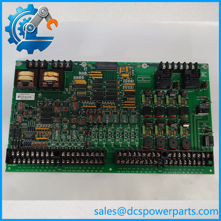
In an LCI control cabinet, auxiliary voltage measurements, current signals, and contact signals must reach the control processor in a form that can be measured and interpreted correctly. The GE DS200DDTBG1A provides the terminal connections and signal-conditioning functions for this interface. Rather than acting as a standalone PLC CPU, it operates as part of the LS2100 control architecture, connecting field wiring to the associated ADMA circuitry and DSPC processor.
The DS200DDTBG1A supports multiple signal types, including high-voltage AC inputs, current-measurement inputs, low-level signals, configurable 4–20 mA current-loop inputs, and analog outputs. Published technical descriptions also identify 12 three-pin jumpers, 33 test points, and 17 LEDs for configuration and diagnostic work. These details make board revision and jumper configuration important during replacement. The G1 version has functional differences from the G2 version, so DS200DDTBG1A should not be assumed interchangeable with DS200DDTBG2A without checking the application and the GEI-100219 manual.
Key technical specifications
| Parameter | Specification |
|---|---|
| Product model | DS200DDTBG1A |
| Manufacturer | General Electric (GE) |
| Functional acronym | DDTB |
| Product type | LCI auxiliary I/O terminal board |
| Control system | GE LS2100 LCI |
| Associated module | DS200ADMA analog-to-digital module |
| Processor association | DS200DSPC digital signal processor board |
| Power source | Supplied through the connected ADMA assembly |
| Analog output channels | Four buffered voltage outputs documented |
| Current-loop input | Configurable 4–20 mA input capability |
| Configuration hardware | 12 three-pin jumpers documented |
| Diagnostic points | 33 test points reported |
| Status indicators | 17 LEDs reported |
| Field connections | Screw-terminal connections for supported signal types |
| Technical reference | GEI-100219; GEH-6373 for LCI system context |
Specification note: Exact channel assignments and supported functions depend on the board revision and jumper configuration. Published listings contain inconsistent power and temperature figures; confirm electrical limits against the applicable GE documentation and board markings rather than applying generic values.
Major features and advantages
1. Multiple auxiliary signal types
The DDTB terminal board accommodates several types of auxiliary field signals used by the LCI control system. These include AC voltage measurements, current measurements, low-level signals, and current-loop signals. This allows the associated control electronics to receive measurements from different parts of the installation through a purpose-built interface.
DS200DDTBG1A
2. Signal conditioning and scaling
The board provides signal conditioning, scaling, and buffering between external wiring and the ADMA circuitry. These functions help adapt field signals for the connected control electronics. Correct wiring and configuration remain essential: a signal connected to the wrong terminal or processed with an incorrect jumper setting may produce invalid measurements or unexpected control behavior.
3. Configurable current-loop inputs
Published descriptions document jumper-based reassignment of selected current-measurement channels for 4–20 mA input use. This is useful when the system design calls for current-loop measurements, but the installed configuration must be checked before wiring changes or replacement. Do not copy jumper positions from another unit without confirming the circuit configuration.
4. Practical diagnostic access
The reported LEDs and test points provide maintenance personnel with visual indications and measurement locations for troubleshooting. These features can assist with investigating signal-path faults, incorrect wiring, or abnormal measurements. LED states should be interpreted using the relevant system documentation; they do not independently establish that every channel is functioning correctly.
5. Integration with the existing control architecture
The board is designed to work with associated LS2100 hardware, including the ADMA module. This makes exact part identification important when maintaining legacy LCI equipment. Replacing the terminal board alone will not resolve a fault caused by the connected ADMA module, DSPC processor, field wiring, or application configuration.
Application scenarios and common pain points
- LCI drive and static-starter systems: Auxiliary signal termination and measurement interfacing within compatible GE LS2100 installations.
- Industrial drive maintenance: Replacement of a faulty terminal board when the original hardware arrangement must be retained.
- Electrical signal troubleshooting: Inspection of auxiliary analog and current-measurement paths using documented test points.
- Legacy system refurbishment: Preservation of the original control architecture where an exact board revision is required.
Common maintenance problems include incorrect signal scaling, current-loop readings outside the expected range, loose field wiring, damaged terminals, abnormal LED indications, and communication or measurement faults traced to associated hardware. The correct troubleshooting approach is to compare field measurements with the expected values at the relevant test points and then isolate the fault across the terminal board, ADMA assembly, processor, and external wiring.
Related products
The following models are related to the same LCI hardware architecture or may be relevant during a maintenance assessment. Their relationship does not establish direct interchangeability.
| Model | Function or relationship |
|---|---|
| DS200DDTBG2A | G2 version of the DDTB auxiliary I/O terminal board; documented functional differences from G1 |
| DS200ADMA | Associated analog-to-digital module connected to the DDTB |
| DS200DSPC | Digital signal processor control board associated with the ADMA assembly |
| DS200VPBLG2A | LS2100 VME P2 backplane used in the LCI system |
| GEH-6373 | LCI system-level manual reference |
| GEI-100219 | DDTB-specific manual reference |
Engineer’s guide: three checks before ordering
1. Verify the full part number. Match DS200DDTBG1A exactly against the board label. Check the complete assembly marking, revision information, connector arrangement, and any suffixes on the existing board.
2. Review the field wiring and jumper setup. Record the existing terminal connections and jumper positions before removal. Confirm signal type, input range, current-loop assignments, and output requirements against the applicable documentation.
3. Confirm the associated hardware. Check the DS200ADMA and DS200DSPC configuration and investigate whether the original fault could originate elsewhere in the signal path. Confirm that the replacement revision is approved for the installed configuration.
Safety warning: This board may interface with hazardous voltage and current signals. Isolate and verify circuits using the site’s approved electrical safety procedure before handling terminals or changing jumpers.
Frequently asked questions
1. What is the GE DS200DDTBG1A used for?
It is an auxiliary I/O terminal board in the GE LS2100 LCI control system. Its main role is to connect and condition auxiliary field signals for the associated ADMA and DSPC control hardware.
2. Is the a standalone controller?
No. It functions as a terminal and signal-conditioning interface within the larger control assembly; it is not the primary processor board.
3. Does the board support 4–20 mA signals?
Published technical descriptions identify configurable 4–20 mA current-loop inputs. The available channels and their assignments must be checked against the actual board revision and jumper configuration.
4. Can DS200DDTBG2A replace ?
Do not assume so. The G1 and G2 versions have documented functional differences. Confirm the required signal functions and approved revision in GEI-100219 before substituting one for the other.
5. Does the DDTB board have its own independent power supply?
Published descriptions indicate that its power is supplied through the associated ADMA assembly. Verify the actual system wiring and applicable documentation before testing or replacing the board.
6. What should be checked when a replacement board is received?
Inspect the part number, board revision, connectors, terminal condition, visible damage, and evidence of previous repairs. Where possible, request documented inspection and functional-test results relevant to the intended application.
7. What information helps confirm a suitable replacement?
Provide the full model number, revision markings, existing ADMA and DSPC part numbers, required field signal types, jumper configuration, and the nature of the original fault. These details help assess hardware and application compatibility before installation.