Description
Technical Specifications
| Parameter | Specification |
|---|---|
| Manufacturer | GE General Electric |
| Series | Mark V DS200 |
| Model | DS200DCFBG1B |
| Functional Acronym | DCFB |
| Product Type | Power Supply / Feedback Board |
| Primary Application | GE industrial drive systems |
| Input Power | 38 VAC and 115 VAC from control power transformer; application-dependent 24 VDC input |
| DC Outputs | +5 VDC, ±15 VDC, ±24 VDC |
| +24 VDC Rating | Up to 3 A |
| -24 VDC Rating | Up to 1 A |
| +15 VDC Outputs | 0.8 A each |
| +5 VDC Output | 4 A |
| Protective Fuses | FU1, FU2, FU3 |
| Jumpers | 12 configurable jumpers |
| DIP Switches | 7 |
| Status Indicators | 2 red LEDs and 1 neon indicator |
| Test Points | 5 |
| Reference Manual | GEI-100028C |
The manual specifies that the DCFB receives power from the control power transformer and generates the control-level supplies used by the drive.
Product Introduction
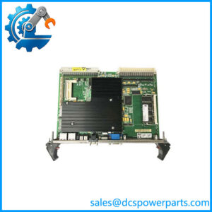
The GE DS200DCFBG1B is a DCFB Power Supply Board used in GE industrial drive systems. Unlike an ordinary standalone power supply, this board combines control-level power generation with several drive monitoring and feedback functions. The original GE documentation identifies the DCFB board for DC2000, CB2000, EX2000, FC2000, GF2000, ME2000, and AC2000 applications.
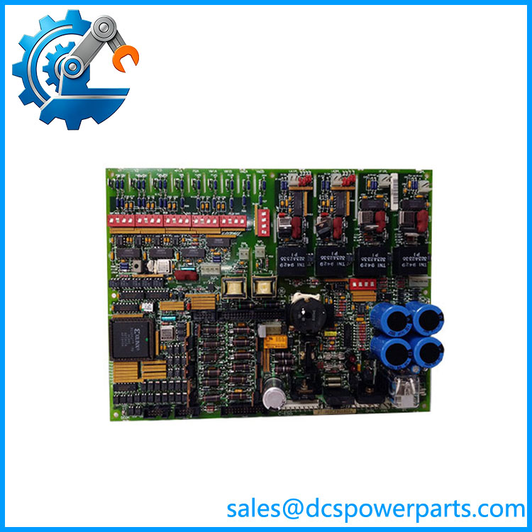
DS200DCFBG1BGB
The GE DS200DCFBG1B DCFB board receives input power from the control power transformer and generates regulated +5 VDC, ±15 VDC, and ±24 VDC supplies for drive control circuitry. The documented ratings include a +24 VDC output of 3 A, a -24 VDC output of 1 A, +15 VDC outputs rated at 0.8 A each, and a +5 VDC output rated at 4 A.
The GE Mark V DS200DCFBG1B also contains circuits associated with motor excitation, gate-pulse generation, and monitoring of AC-line and DC-motor signals. In drive applications, these functions allow the board to participate in the wider control and protection architecture rather than simply supplying voltage to another board.
For legacy GE drive systems, the DS200DCFBG1B is therefore an important board to identify correctly. The final two characters of a GE DS200 board number can distinguish hardware variants, and the original documentation specifically notes that all digits are important when ordering or replacing a board.
Main Features & Field Considerations
Control-level power generation
The DCFB generates the low-voltage supplies required by drive electronics. A failure in one supply can produce symptoms that appear to originate from the drive control card even though the underlying problem is on the DCFB.
Feedback and monitoring circuits
The board includes circuits for monitoring AC-line and motor-related electrical signals. Consequently, troubleshooting should not be limited to checking the output voltages.
Configurable hardware
The board uses configurable jumpers and DIP switches. GE’s replacement procedure specifically instructs technicians to compare jumper and switch positions between the removed and replacement boards.
Protection components
FU1, FU2, and FU3 are identified as user-replaceable fuses. The GE manual states that if other board components fail, the board should be replaced as a complete unit.
Replacement risk
Before installing a replacement, verify:
- Complete DS200DCFBG1B part number
- Board revision and suffix
- Jumper positions
- DIP-switch settings
- Drive model and application
- Incoming control power
- Connected cables and connectors
Safety consideration
This board can contain hazardous voltages when energized. GE’s documentation calls for power removal, capacitor discharge time, and electrical verification before board removal. The board should also be treated as static-sensitive during handling.
Typical Applications
- GE AC2000 drive systems
- GE DC2000 drive systems
- CB2000 drive systems
- FC2000 drive systems
- GF2000 and ME2000 systems
- EX2000 excitation applications
Procurement Note
For the , the safest replacement approach is to match the complete board number and hardware configuration, not simply “DS200DCFB.” The original GE documentation explicitly states that board revisions can contain different hardware and that jumpers and switches must be matched during replacement.