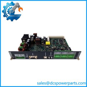
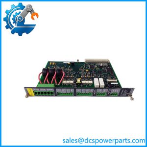
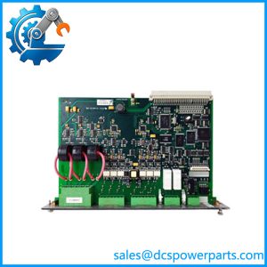
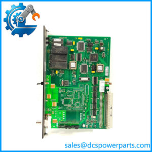
Description
Product Overview
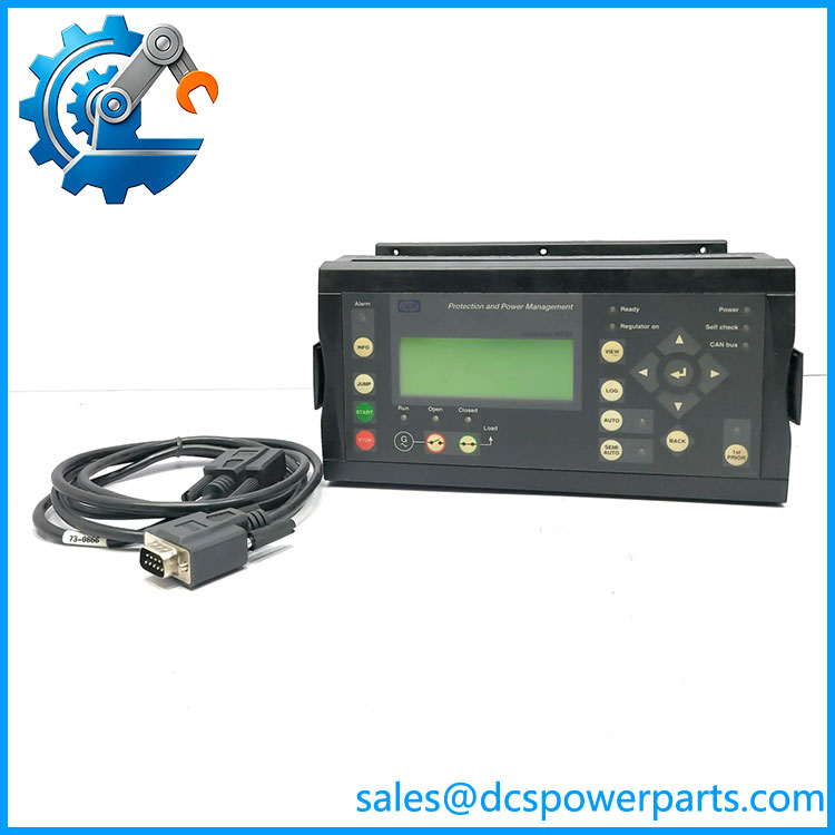
The DEIF PPM-3 is a marine protection and power management system designed to coordinate generator operation and electrical power distribution aboard vessels and offshore installations. It combines generator supervision, electrical protection, automatic synchronization, and load sharing within a distributed controller architecture. The system is designed to manage diesel generators, shaft generators, shore connections, emergency generators, and bus-tie breakers, depending on the installed configuration. It is used where multiple power sources must operate together while maintaining electrical stability and coordinating load demand.
A key feature of the DEIF PPM-3 is its multi-controller architecture. Power management calculations are distributed across the diesel-generator controllers, with a designated command unit handling start priorities and related functions. If that controller becomes unavailable, the calculations can transfer to another available unit. Internal communication uses a dedicated CAN bus; external supervisory integration can use supported interfaces such as Modbus RTU over RS-485, Modbus TCP/IP, or Profibus DP. The internal CAN bus is intended for DEIF equipment and should not be treated as a general-purpose external CAN interface.
For maintenance and procurement teams, the DEIF PPM-3 is most relevant when maintaining an existing marine power management installation. DEIF currently marks the system as not recommended for new designs and identifies the iE 350 Marine as a replacement product. That does not automatically establish a direct retrofit path: controller configuration, application software, I/O assignments, communication settings, protection parameters, and marine approvals must all be reviewed before a changeover. When sourcing a replacement PPM-3 unit, confirm the exact unit designation, hardware revision, installed software version, configuration backup, and condition with the supplier.
Product Introduction
The DEIF PPM-3 is a marine power management and protection system for coordinating generator sets and other shipboard power sources. It supports generator supervision, synchronization, load sharing, electrical protection, and coordinated power distribution.
Its application depends on the selected controller type, system architecture, and configured communication interfaces. Since DEIF no longer recommends PPM-3 for new designs, verify service requirements and migration plans when purchasing units for an installed system.
Key Technical Specifications
| Parameter | Specification |
|---|---|
| Manufacturer | DEIF |
| Model | PPM-3 |
| Product type | Protection and power management system |
| Application | Marine and offshore power systems |
| Control functions | Generator control, supervision, and protection |
| Power management | Automatic synchronization, load sharing, start/stop coordination |
| Maximum diesel generators | Up to 16; up to 15 when an emergency diesel generator is included |
| Shaft generators | Up to 2 |
| Shore connections | Up to 2 |
| Bus-tie breakers | Up to 8 |
| Emergency/harbor generator | Up to 1 |
| Measuring voltage | 100–690 V AC, ±20%, subject to wiring configuration and derating |
| Measuring current | 1 A or 5 A CT secondary |
| Measuring frequency | 30–70 Hz |
| Auxiliary supply | 12/24 V DC nominal; operating range 8–36 V DC |
| Binary inputs | 8–36 V DC ON signal |
| Analog inputs | Configurable options include 0/4–20 mA, 0–40 V DC, and speed pickup input |
| Relay outputs | Up to 250 V AC / 30 V DC, 5 A; applicable ratings depend on listing and load |
| External communications | Modbus RTU, Modbus TCP/IP, Profibus DP, depending on configuration |
| Internal communication | Dedicated DEIF CAN bus |
| Operating temperature | −25°C to +70°C; certain configurations/options have a lower limit |
| Mounting | DIN rail or base mounting, depending on unit |
| Front protection | IP54 with seal reported in technical references; confirm the exact enclosure and installation |
| Product status | Not recommended for new designs |
| Condition | Confirm actual condition with supplier |
Specifications are drawn from DEIF documentation and technical references. Confirm the precise controller variant, options, and ratings against the applicable data sheet before installation.
Related Products
| Product | Relationship |
|---|---|
| DEIF iE 350 Marine | DEIF-identified replacement product for the ; application engineering is required before migration. |
| DEIF iE 250 Marine | Current marine power management product to evaluate for applicable systems; not a guaranteed direct replacement. |
| DEIF PPM 300 | Related protection and power management platform for marine and offshore applications. |
| DEIF AGI 400 | Graphical operator interface product that may be relevant to broader DEIF monitoring and control systems; confirm system-level compatibility. |
| DEIF Multi-line 2 PPM application software | Software family associated with ; confirm the installed software revision and compatibility before service work. |
Frequently Asked Questions
Q1: Can the DEIF be hot-swapped?
Do not assume that it can. Controller removal can interrupt generator supervision, protection, or power management. Follow the approved vessel-specific procedure, establish any required backup control, and isolate power as specified by DEIF documentation.
Q2: Does the require specific software?
Yes. The installed application software and configuration matter. Confirm the software revision, controller role, parameter set, and compatibility with the existing system before replacing a unit. Retain a verified configuration backup where available.
Q3: Is the compatible with all DEIF controllers?
No universal compatibility should be assumed. Check the system architecture, controller designation, firmware/software versions, communication setup, and installed I/O. Shared branding does not establish interchangeability.
Q4: Can the be replaced by the iE 350 Marine?
DEIF identifies the iE 350 Marine as a replacement product, but this does not mean a plug-in or one-to-one substitution is guaranteed. Assess I/O mapping, generator control logic, protection settings, communications, commissioning requirements, and applicable marine approvals before planning a retrofit.
Q5: Could replacing the controller cause parameter or configuration loss?
Yes, if the configuration is not transferred or restored correctly. Back up the existing parameters and application data, document communication settings and I/O assignments, and validate protective functions during recommissioning.
Q6: How should buyers verify condition and authenticity?
Request the complete nameplate and model designation, hardware revision, software version where accessible, photographs of terminals and connectors, and available test or service records. Confirm whether the unit is new, used, repaired, or refurbished; do not infer condition from the model name alone.
Q7: What should be checked before returning a system to service?
Verify controller communication, generator measurement signals, synchronization, load-sharing behavior, breaker control, alarm handling, and all configured protective functions. Test according to the vessel’s approved commissioning and safety procedures rather than relying solely on a successful controller power-up.