Description
Product Overview
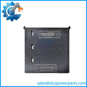
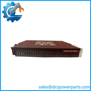
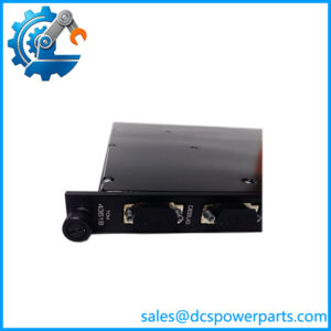
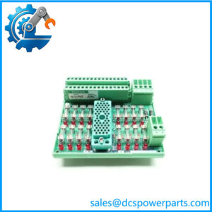
AI2351 7400210-010 is the standard analog input baseplate of the Trident safety controller, and it is the piece of the system that most analog troubleshooting actually lands on. The two numbers belong together: AI2351 is the Model 2351 designation used in drawings, in the Product Specifications and in TriStation configuration, while 7400210-010 is the ordering number that appears on the label and the invoice. Buyers who treat them as two different parts either order a module they did not need or receive a baseplate they cannot identify.
Functionally, the baseplate is the carrier for an I/O set: two slots marked L and R, each able to hold a Model 3351 Analog Input Module, one active and one hot-spare, with mechanical keying that stops a module being seated in a baseplate configured for something else. All thirty-two field terminations land on its compression terminals — 24 to 12 AWG, 0.2 to 3.3 mm² — and the kit ships complete, with the I/O interconnect assembly 2921, slot cover 2900 and terminal cover 2901. The interconnect assemblies chain baseplates into a column and carry both I/O bus messages and logic power; logic power originates on the MP baseplate as redundant fused 24 VDC and reaches every I/O position through that chain, so an analog column needs no separate logic supply.
The electrical detail that distinguishes the 2351 from the HART and external-termination variants is the input path. Triconex quotes the Model 3351 module’s input impedance as 250 Ω with baseplate, against a 180 Ω source impedance, with a 100 Ω 0.01 % I-to-V resistor in the measuring chain. In other words, the 4–20 mA loop is completed on the baseplate, not inside the module — which is why a baseplate cannot be treated as a passive piece of plastic. It also fixes the point style: thirty-two commoned points, meaning the returns share a reference. A plant that needs individually floating inputs, thermocouples, RTDs with their own cold-junction handling, or HART pass-through is not served by this baseplate; those requirements map to Model 2352 with its external termination panels, or to 2354 and 2354A for HART.
Mechanically, the 2351 is an I/O baseplate at 178 × 249 mm, in contrast to the 229 × 249 mm footprint of the MP and HART baseplates — a difference that shows up immediately when someone tries to fit an MP interconnect assembly to an I/O position. All Trident I/O modules are 44 × 220 × 169 mm with a 70 °C ambient limit, and the I/O bus runs at 2 Mbit/s TMR HDLC over the interconnect chain.
The reseller layer around this number is, as usual, unusable. AI2351 7400210-010 is sold as a “next-generation modular industrial automation controller” with an Intel Xeon processor and 64 GB of DDR4, as a general-purpose I/O module with unspecified channel counts, and in lists that mix it with the -100 and -101 variants of the same ordering block. The baseplate carries its own identity in silkscreen — 3000675-010 for Model 2351 — and that number, plus the kit contents, is what settles any question about what is in the box.
Technical Specifications
| Parameter | Value |
|---|---|
| Model / ordering number | Triconex AI2351 = Model 2351; ordering number 7400210-010 |
| Manufacturer / platform | Triconex, Invensys; now Schneider Electric — Trident (Trident v2) TMR safety controller |
| Item class | Analog input baseplate kit — passive carrier, no module electronics |
| Baseplate assembly number | 3000675-010 (I/O baseplate) |
| Kit contents | I/O baseplate; I/O interconnect assembly 2921; slot cover 2900; terminal cover 2901 |
| Point configuration | 32 points, commoned (one shared return reference) |
| Input path | 250 Ω input impedance with baseplate; 180 Ω source impedance; 100 Ω 0.01 % I-to-V resistor |
| Compatible module | Model 3351 Analog Input Module — 4–20 mA nominal, 2–22 mA operational range, 33 VDC absolute maximum field voltage |
| Module performance | 12-bit resolution; absolute error 0.15 % of full scale (20 mA); 16 Hz input bandwidth; scan < 1 ms for all 32 points |
| Diagnostics | Force-to-value diagnostic (FVD) per channel; fault per channel, not per module |
| Slots and redundancy | 2 slots (L and R) per baseplate; active / hot-spare; mechanically keyed |
| Field terminals | Compression terminals, 24 to 12 AWG (0.2 to 3.3 mm²) |
| Logic power and bus | Redundant fused 24 VDC from MP baseplate (19.2 to 30 VDC, 5 % ripple); TMR HDLC I/O bus at 2 Mbit/s |
| Dimensions and environment | Baseplate 178 × 249 mm (7.0 × 9.79 in); modules 44 × 220 × 169 mm; 70 °C maximum ambient |
| Isolation | Functional earth to protective earth 500 VDC min; functional earth to functional earth (logic) 800 VDC min |
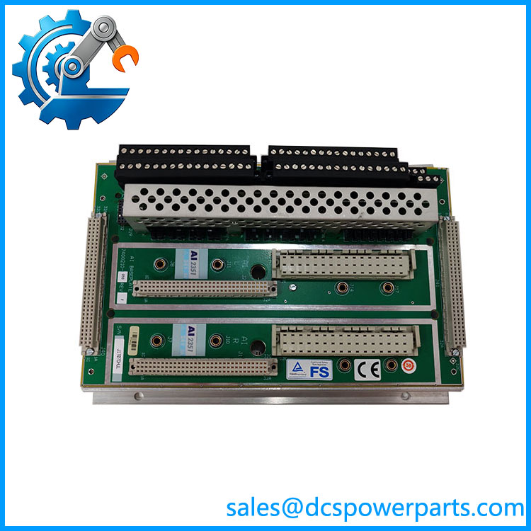
TRICONEX AI2351 7400210-010
Key Features and Advantages
The burden lives on the baseplate: Triconex states the 3351 module’s 250 Ω input impedance as a figure with baseplate, so the current-sense path is completed by the carrier rather than the plug-in card. That is why a 2351 baseplate is a specified electrical component and not a mounting bracket — and why substituting a different baseplate model changes the measurement, not just the wiring.
Thirty-two points on one carrier: a full analog input set occupies a single baseplate with active and hot-spare modules, which keeps marshalling compact and keeps the number of interconnect joints down. On a column with many loops, that density is what allows a modest panel footprint to carry the whole analog scope.
Commoned returns, stated plainly: the thirty-two points share a reference. This is efficient for transmitters fed from a common isolated supply, and it is the wrong baseplate for floating sources or thermocouples. Reading that constraint before ordering prevents the most common mis-purchase in this family.
Per-channel fault reporting: the Model 3351 module carries complete ongoing diagnostics on each channel and turns on the Fault indicator for a channel fault rather than declaring the module dead, with a force-to-value diagnostic proving the input path. On a live plant, that distinction decides whether a technician pulls a module or a loop.
Twelve bits at 0.15 % of span, in under a millisecond: the specification suits fast pressure, level and flow loops and still leaves headroom for the 2–22 mA window that makes an open loop visible as an under-range reading rather than a plausible zero.
Wiring that outlives the module: terminals on the baseplate, keying that refuses a wrong module, and an interconnect chain that carries power and bus mean a module replacement is a lift-and-seat operation with no conductor touched. The 2351 stays in place for the life of the column.
Protection delivered with the kit: interconnect, slot cover and terminal cover arrive together, so a replacement restores the assembly’s protection against dust, liquids and corrosive atmospheres instead of leaving an open slot in a plant atmosphere where creeping terminal resistance is the normal failure mode.
Honest limits: no HART pass-through, no per-point isolation, no thermocouple or RTD provision, and no field wiring on the module itself. Those needs belong to 2354, 2354A, 2352 or an external termination panel — not to this kit.
Applications
Refinery and petrochemical analog input marshalling: 4–20 mA transmitters for pressure, level, flow and analysers, thirty-two loops to a baseplate, with the 2–22 mA range and per-channel diagnostics turning a failed transmitter into a named point rather than a silent offset in the control room.
Emergency shutdown and burner management analog channels: process inputs that feed the safety logic — drum level, fuel pressure, flame-related signals — where a channel fault must be distinguishable from a module fault so the correct spare is pulled during a trip investigation.
Gas turbine and compressor packages: analog inputs for lube-oil pressure, vibration-adjacent process signals, suction and discharge pressures on anti-surge control, where sub-millisecond scan across the full point set keeps the loop timing predictable.
Power generation balance-of-plant: feedwater, condensate and cooling-water transmitter inputs on a Trident column that has been in service for decades, where the practical question is not which module to buy but which baseplate model each position already holds.
Brownfield retrofit and column expansion: adding an analog set to an existing column means adding a 2351 with its interconnect, carrying logic power and I/O bus onward, and re-terminating field loops on compression terminals — the baseplate kit is what the scope is built around, not the module.
Obsolete-platform support: sites maintaining Trident systems where 2351 baseplates are already installed, re-terminating after an enclosure rebuild or replacing a damaged carrier while reusing the modules and the field wiring schedule.
Related Products
Model 3351 Analog Input Module — the only module type this baseplate is configured for; 32 commoned 4–20 mA points, 12-bit, FVD diagnostics. 5351 Analog Input TriPak — the packaged combination of one Model 3351 module and one AI2351 Model 2351 baseplate kit, the standard way this pair is ordered as a set. 2352 Analog Input Baseplate Kit (TC, RTD, 4–20 mA) — external-termination variant for thermocouples and RTDs, requiring two Model 9764-510 termination panel kits; the alternative when commoned 4–20 mA is not enough. 2354 Analog Input HART Baseplate Kit — adds HART pass-through to Configuration and Asset Management Software; the baseplate to specify for smart transmitters. 2354A Analog Input HART Hazardous Location Baseplate Kit (ATEX) — the hazardous-area version of 2354, on the larger 229 × 249 mm footprint. 2361 Analog Input/Digital Input Baseplate Kit — mixed baseplate for the Model 3361 module (16 DI plus 16 AI); the choice when a cabinet position must carry both signal types. 7400209-010 Model 2481 Analog Output Baseplate Kit — the analog output counterpart in the same 7400 ordering block, for the loops this baseplate reads. 7400208C-020 Model 2301 Digital Input Baseplate Kit — discrete input carrier of the same column, sharing the interconnect chain and logic power. 2921 I/O Interconnect Assembly — the passive link that carries I/O bus messages and logic power from one baseplate to the next; supplied with the kit. 2281 I/O Bus Extender Module Kit — used where the I/O bus must reach a separate column, with 2-ft I/O bus cable sets.
Installation and Maintenance
Before installation: confirm the baseplate is a AI2351 7400210-010 by its 3000675-010 assembly number rather than by the seller’s description, and check that the kit contains the interconnect assembly 2921, slot cover 2900 and terminal cover 2901. Establish that the thirty-two points will be commoned — if any loop must float, or needs HART or a thermocouple, this is the wrong baseplate and 2354 or 2352 is the right one. Verify the module to be seated is a Model 3351 and that its keying matches, and confirm logic power reaches the position through the interconnect chain from the MP baseplate.
Installation: mount the baseplate vertically on the panel with airflow clearance and wiring channels along the column, connect the interconnect assembly, and carry the chain to the next baseplate. Terminate the 4–20 mA loops on the compression terminals at 24 to 12 AWG, keeping shields bonded at the cabinet entry and the common return consistent across all thirty-two points. Fit slot cover and terminal cover before energising. Because the burden is on the baseplate, check each loop with a meter at the terminals — supply present, return continuous — before the module is seated; a wiring error will otherwise be reported as a channel fault.
Maintenance: inspect compression terminals on planned outages for loosened strands, discolouration and corrosion, and re-torque to specification; a drifting analog reading on one point with a healthy module usually traces to terminal resistance rather than electronics. Confirm both interconnect ends are fully seated — a partially seated assembly produces intermittent I/O across the whole set. Use the module’s per-channel diagnostics to separate channel faults from module faults before swapping hardware, and keep the terminal covers fitted: on a assembly, an uncovered terminal block in a corrosive atmosphere is the usual origin of slow measurement drift. Photograph the assembly number of each baseplate for the as-built record so the next purchase order matches the slot.
Warranty and Quality
Each 7400210-010 is supplied as the Trident Model 2351 Analog Input Baseplate Kit — baseplate 3000675-010 with interconnect assembly 2921, slot cover 2900 and terminal cover 2901 — and is identified by that assembly number before dispatch, because this ordering number is routinely sold online as a general-purpose controller or an unspecified I/O module with processor and memory specifications that belong to no Triconex product. Every unit is inspected for baseplate flatness and connector condition, terminal block integrity and corrosion, interconnect seating, keying, and completeness of the slot and terminal covers, with any sign of prior re-termination or field repair noted. Where a Trident bench is available, the baseplate is populated with a Model 3351 module pair, powered through the column interconnect, driven across 4, 12 and 20 mA on representative points against the published 250 Ω input path, and checked for clean active/hot-spare transfer and for correct force-to-value diagnostic response. A 12-month repair, replacement or refund commitment applies. Technical support covers the questions this part actually raises: distinguishing 2351 from 2352, 2354 and 2354A, confirming commoned-point suitability for a given transmitter scheme, matching the correct module and keying, and closing the gap between an ordering number and a Model designation on a site drawing.