Description
Product Overview
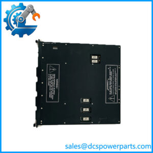
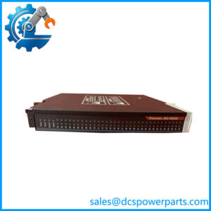
AO3481 is one of the two analog output modules of the Trident v2 safety controller — the current-loop version, with four points, and the one that most Trident installations actually use. Inside it are three independent sets of electronics, one per processor channel, each receiving the same output demand from its MP. A voter circuit then picks one channel to drive the field loop and shunts the output of the other two, so the loop is always driven by a single leg while the other two remain live and ready.
That arbitration is the part worth understanding, because it explains the module’s two most quoted promises. First, the driving channel rotates: the module periodically hands the loop to a different leg and checks the one it just released. All three legs are therefore exercised and proven without any disturbance to the 4–20 mA signal the plant sees. Second, because the module runs a forced-switch diagnostic on each point and compares the legs, Triconex specifies that each AO module remains in calibration for the life of the controller — no periodic manual calibration. On a safety system, that is not a convenience; it removes a maintenance activity that would otherwise require putting a final element at risk.
The output stage is deliberately simple in a way that has real design consequences: four points, commoned return, DC-coupled, and — in the official wording — no isolated points. All four loops share a return. That buys density and a smaller baseplate footprint, and it means the module suits a marshalling scheme where the four final elements share a common reference. A plant that needs channel-to-channel isolation on its analog outputs is asking this module for something it does not provide, and the HART baseplate variants do not change that: 2483 and 2483A add HART communication to smart positioners, not point isolation.
Field wiring does not come to the module at all. As with every Trident I/O module, the terminals are on the baseplate — 2481 in a standard cabinet, 2483 where HART is needed, 2483A for HART in a hazardous location, or the DO external termination baseplate with the 9863-610 panel for hazardous-area work. The module carries the front panel and a lock lever, is mechanically keyed against wrong-baseplate installation, and supports a hot spare. Swapping one therefore breaks no loop wiring.
One capacity rule catches people late in a project: a Trident controller takes up to 14 I/O modules, but only 10 if analog output or pulse input modules are included. Two AO modules in the same column can push a design past the limit sooner than the point count suggests.
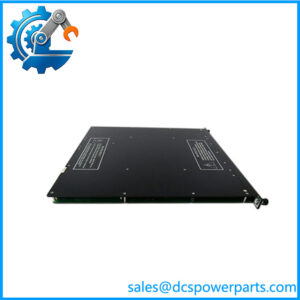
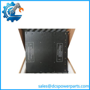
Finally, the name. The product is officially the Model 3481 Analog Output Module; suppliers list it as AO3481. It is a Trident module, not a Tricon v9/v10 analog output (3805E) — a substitution that will not fit the baseplate — and any page describing it as a 220 V controller with an output frequency is describing something that does not exist.
Technical Specifications
| Parameter | Value |
|---|---|
| Model / official designation | AO3481 — Triconex Model 3481 Analog Output Module |
| Manufacturer / platform | Triconex, Invensys; now Schneider Electric — Trident v2 safety controller |
| Module type | Analog output, TMR; 4 points, commoned return, DC-coupled; isolated points: none |
| Output current range | 4–20 mA controlled, 0–22 mA over-range; 0 mA output capability (step function < 2 mA) |
| Accuracy and resolution | < 0.25 % of FSR (0–22 mA) over 4–20 mA, from 0 to 70 °C; 12-bit resolution |
| Diagnostics | Forced-switch diagnostic per point; rotating drive channel exercises all three legs; front-panel PWR/LOAD field alarm |
| External loop power | 24 VDC nominal, 32 VDC maximum, reverse-voltage protected |
| Load capability | 300 Ω at ≥ 16 VDC; 500 Ω at ≥ 20 VDC; 700 Ω at ≥ 24 VDC; 800 Ω at ≥ 28 VDC (supply rated 1 A minimum) |
| Protection and switching | 36 VDC continuous over-range protection, 0 VDC continuous; switch time on leg failure 1 ms typical, 3 ms maximum |
| Isolation | Functional-to-protective-earth 500 VDC minimum; functional-to-functional-earth (logic) 800 VDC minimum |
| Baseplates and packaging | Model 2481 standard; 2483 HART; 2483A HART hazardous location; DO external termination baseplate with 9863-610 for hazardous areas; hot-spare capable, mechanically keyed, lock lever |
| Mechanical and environment | 44 × 220 × 169 mm (W × H × D); −20 to +70 °C ambient, 5–95 % RH non-condensing; system limit 14 I/O modules, 10 when AO or PI modules are used |
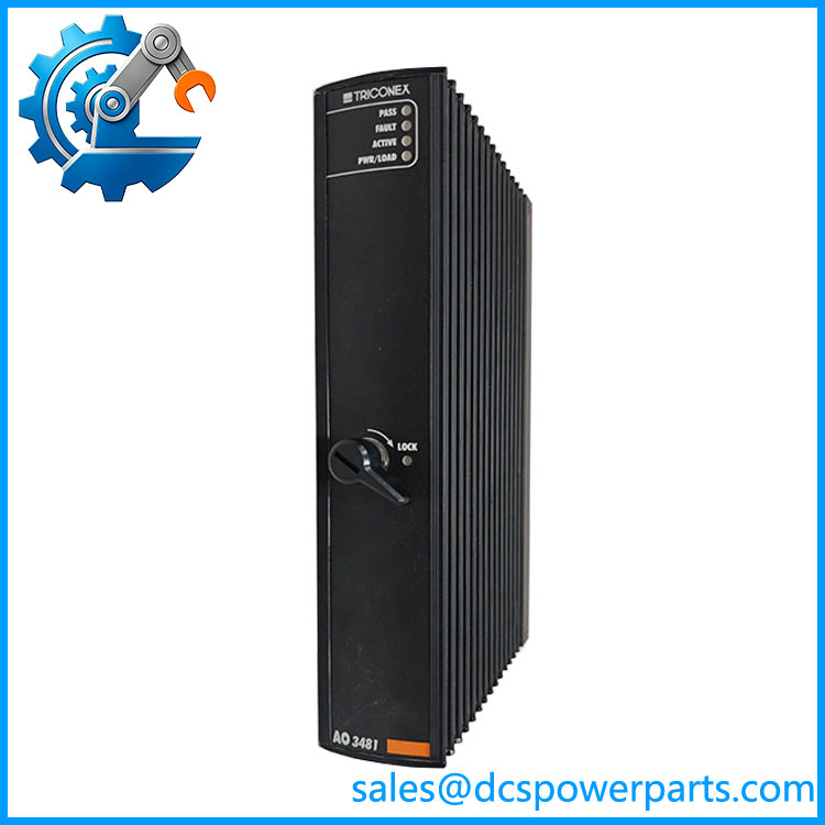
AO3481
Key Features and Advantages
Voting that keeps proving itself: the voter selects one channel to drive the loop and shunts the other two, and the selection rotates. Nothing is taken offline to be tested, and no leg goes unproven — the module conducts its own proof test continuously, in the background, on a live loop.
Calibration removed from the maintenance calendar: because each point is force-switched and the legs are compared, the module is specified to stay in calibration for the life of the controller. On a plant where every calibration visit means a final element driven away from its working position, eliminating that activity changes the turnaround plan, not just the paperwork.
A load table that answers the loop-power question before installation: 300 Ω at 16 VDC, 500 Ω at 20 VDC, 700 Ω at 24 VDC, 800 Ω at 28 VDC, each with a supply rated at 1 A minimum. A 700 Ω positioner on a 24 VDC loop supply sits exactly at the published capability, which is why the supply voltage is a design decision rather than an afterthought.
Commoned return, stated plainly: four points share a return and there are no isolated points. Density and a smaller baseplate are the gain; shared reference is the constraint. Where four valves or actuators already sit on a common marshalling return, this is the correct part; where each loop must float independently, it is the wrong one, and no HART baseplate changes that.
Fault reporting that tells a technician which side to look at: PASS, FAULT and ACTIVE cover the module, and the PWR/LOAD indicator raises a field alarm for an open load or an out-of-compliance condition — the two failures that look identical on a chart and are diagnosed differently with a voltmeter at the terminals.
Serviceable without touching a single loop: terminals are on the baseplate, the module is keyed and lock-levered, and a hot spare can be carried. Replacement is a module lift, and the loop wiring, shields and terminations stay exactly as they were.
Fast enough to be invisible on failure: switch time on leg failure is 1 ms typical, 3 ms maximum, which is why a single channel fault appears in the logs as a diagnostic rather than as a process upset.
The honest limits: four points, commoned, no point isolation, and the 10-module column limit when AO modules are present. Those constraints belong in the selection decision, not in the commissioning week.
Applications
Final control elements in an ESD system: shutdown valves, trip valves and vent valves driven by 4–20 mA positioners or I/P converters, where the demand must survive the loss of any one processor channel. The rotary voting means a valve stays at its commanded position through a channel fault, with the fault reported rather than propagated.
Burner and furnace management: fuel control valves, air dampers and igniter positioning on a BMS, where the output must not drift and where a calibration visit is an outage. The no-recalibration specification is the reason this module appears in combustion packages.
Turbine and compressor auxiliary control: anti-surge recycle valve positioning, lube-oil pressure control valves and governor bias signals, with 12-bit resolution and the 300–800 Ω load window matching the actuators usually found on those skids.
Smart positioners and HART diagnostics: on a 2483 or 2483A baseplate, the same module type carries HART communication to valve positioners, so a control room can read positioner diagnostics without a separate multiplexer. The hazardous-location variant is the one to specify for a Zone 2 or Division 2 field area.
Retrofit of an existing Trident column: modules being replaced one at a time on a running controller, where the baseplate stays in place and the loop wiring is untouched. This is where hot-spare capability and keying do their real work.
Replacement of a Tricon-era analog output: a site consolidating onto Trident, or holding spares for both platforms. The two are not interchangeable — Tricon v9/v10 output modules are different parts on different baseplates — and matching the platform before ordering is the whole job.
Related Products
3482 High-Current Analog Output Module — same family, two 4–20 mA points plus two 4–40 mA high-current points; the choice when an actuator needs more drive current. 2481 Analog Output Baseplate Kit — the standard baseplate that carries the terminals and connectors for AO3481; a module without it has no field wiring. 5381 Analog Output TriPak — the packaged combination of one Model 3481 module and one 2481 baseplate kit. 2483 Analog Output HART Baseplate Kit — adds HART communication to smart positioners; the baseplate to specify when valve diagnostics are required. 2483A Analog Output HART Hazardous Location Baseplate Kit — the ATEX variant of the HART baseplate, with intrinsic-safety barriers for field areas. 9863-610 Analog Output Termination Panel Kit — external termination panel used with the DO external termination baseplate for hazardous-location analog output. 3351 Analog Input Module — the matching analog input of the same platform, on baseplates 2351 / 2352 / 2354; the module pair that most loops are built around. 3401 Digital Output Module — same-generation discrete output, mounted on its own baseplate; the module to compare when a final element could be driven either way. 3451 Solid-State Relay Output Module — 32-point relay-style output of the same platform, for on/off final elements rather than modulating ones. 3101 Main Processor Module and 3201 Communication Module — the processors AO3481 takes its demand from, and the gateway that reports its diagnostics outward.
Installation and Maintenance
Before installation: confirm the platform first — AO3481 is a Trident module for baseplate 2481 (or 2483/2483A for HART), not a Tricon v9/v10 output module and not a 3482, whose point configuration differs. Verify the column budget, since a Trident controller accepts 14 I/O modules but only 10 when analog output or pulse input modules are included. Then size the loop supply against the published load table — 300 Ω needs 16 VDC, 500 Ω needs 20 VDC, 700 Ω needs 24 VDC, 800 Ω needs 28 VDC, at 1 A minimum — and confirm the four points can share a common return, because they do.
Installation: mount the baseplate, terminate the four loops and their common return, bond the shields at the cabinet entry, and keep the loop conductors clear of drive and switching cables. Check the field circuit with a meter before the module is seated — an open loop or a shorted positioner will otherwise appear as a module fault. Fit the module, confirm the lock lever engages and the keying aligns, then apply loop power and watch the front panel: PASS steady, ACTIVE indicating scan activity, and no PWR/LOAD alarm on any point. Since the module requires no calibration, commissioning is a verification exercise — drive each point to 4, 12 and 20 mA and confirm the reading at the field device — not an adjustment.
Maintenance: the routine is inspection rather than tuning. Read the panel before reaching for a laptop: a FAULT with healthy field power points at the module, a PWR/LOAD alarm points at the loop — an open load or a compliance error, both diagnosed with a voltmeter at the baseplate terminals. Keep a hot spare and use it: replacement breaks no wiring because the terminals live on the baseplate, and the module is keyed so it cannot be seated on the wrong baseplate. Log every leg-failure switch time reported by diagnostics; a module that switches cleanly in 1–3 ms is behaving, while repeated switching on one point usually means a marginal loop rather than a failing module. Do not attempt field calibration — there is none to perform, and adjusting a loop to compensate for a drifting positioner hides the fault that the diagnostics are trying to report.
Warranty and Quality
Every is supplied as the Triconex Model 3481 Analog Output Module — four 4–20 mA points, commoned return, TMR with forced-switch diagnostics, for baseplate 2481 and the HART variants 2483/2483A — and is identified as such before dispatch, because this part number is routinely mis-sold as a controller with a mains supply and an output frequency, or confused with the Tricon-era output module that will not fit a Trident baseplate. Each unit is inspected for front-panel and housing condition, baseplate connector and lock-lever integrity, keying, indicator operation, and evidence of prior repair, heat damage or moisture ingress. Where a Trident bench is available, the module is seated on a 2481 baseplate with a 24 VDC loop supply, driven across 4, 12 and 20 mA on all four points against a resistive load inside the published window, checked for accuracy within 0.25 % of span, exercised for PWR/LOAD alarm response on an open loop, and observed for clean leg switching. A 12-month repair, replacement or refund commitment applies. Technical support covers what this platform actually raises: choosing between 3481 and 3482, wiring a commoned return without creating a ground loop, sizing loop power from the 300–800 Ω table, and respecting the ten-module column limit that catches projects at the end rather than the beginning.