Description
Product Overview
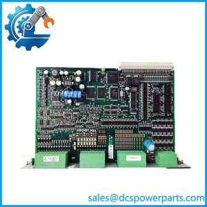
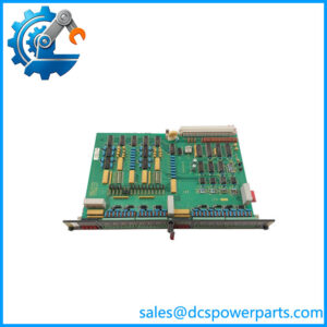
IPM-1 is the input module of DEIF’s DELOMATIC 3 — the DM-3 multi-function system that sat underneath ship power management and land-based multi-genset plants for a long generation of installations. It is a plug-in board for the DGU rack, not a standalone device: 6 TE wide, 30.5 mm across, 0.40 kg, seated in a backplane slot next to a CM-2 control module, and supplied from the rack’s PSM-1 power module rather than from its own terminals.
Its job is unglamorous and central. Sixteen channels, each independently configured as a binary input for a potential-free contact, an analogue current input, or an analogue voltage input. Everything a DGU needs to know that is not a three-phase measurement arrives through this board: breaker and contactor status, running and ready signals, tank level switches, pressure and temperature transmitters, remote start and stop commands, fuel and lube-oil conditions. The SCM-1 and SCM-2 modules handle volts, amps and phase angle; the IPM-1 handles everything the plant’s own devices have to say.
The configuration model is where most field confusion starts. The channel type is set in the application program running in the CM, and the module’s own hardware must match it — a channel defined as a 4–20 mA input in the application and wired as a dry contact, or the reverse, produces readings that look plausible and are meaningless. Analogue live zero is likewise not a jumper: a 2–10 V or 4–20 mA offset range is established by the application program, not by the module. That is DEIF’s design choice — one board type covers all 16 channels, and the specificity lives in software that is backed up and version-controlled.
Diagnostics are deliberately sparse. The sixteen LEDs numbered 1 to 16 are active only when the corresponding channel is configured as a binary input, and light to show that input is at CC — closed contact. An analogue channel has no LED at all, and a channel with an open field circuit and no cable supervision shows nothing whether the loop is healthy or broken. The board is meant to be read through the DGU and the control panel, not through the front of the module.
Electrically, the board is common-ground by design: in all three configurations, every “COM” terminal is tied to the module’s internal ground. The 1.0 kV test voltage covers channel-to-backplane and chassis isolation, not channel-to-channel. For a cabinet full of loop-powered transmitters referenced to the same 0 V this is exactly right and saves a great deal of wiring; for a design that expects floating inputs on sixteen independent signals, it is a constraint that has to be discovered before the cabinet is built, not after.
Performance is adequate for plant signals and unsuitable for protection. Accuracy is Class 1 to IEC 688 over -10 to +55 °C, resolution 0.1 % of full scale, analogue input impedances of 50 Ω on current and 15 kΩ on voltage, and an ON/OFF response of 20 ms plus one scan — up to about 130 ms. That number decides where the module may be used: it belongs on status, commands and process values, not on an interlock path that must act in milliseconds.
DEIF has since placed DM-3 at end of life, and the official position is that there is no direct replacement. IPM-1 therefore matters today as an installed-base component: the board that keeps an existing DGU rack alive when a channel dies, ordered against the rack’s configuration rather than against a generic “16-channel input module” description.
Technical Specifications
| Parameter | Value |
|---|---|
| Model / part number | IPM-1, assembly code 1044220070E |
| Manufacturer | DEIF A/S, Denmark |
| Product type | Universal input module for the DELOMATIC 3 DGU rack |
| Channel count | 16, individually configurable |
| Channel types | Binary input (potential-free contact), current input 0–20 mA, voltage input 0–10 V |
| Live zero | 2–10 V / 4–20 mA ranges established by the application program in the CM |
| Supply | From the PSM-1 power module via the rack backplane |
| Power consumption | 1.5 W typical, 3 W maximum |
| Isolation | 1.0 kV, 50 Hz, 1 minute, to GL / LR / DNV test practice |
| Accuracy | Class 1 per IEC 688, -10 to +55 °C; resolution 0.1 % of full scale |
| Input impedance | 50 Ω current input, 15 kΩ voltage input |
| Binary threshold | ON detection up to 250 Ω; cable supervision shunt 3.3 kΩ ±10 % |
| Response | 20 ms plus one scan, 130 ms maximum |
| Dimensions / weight | 30.5 mm wide (6 TE); 0.40 kg |
| Environment / protection | Reference 15–30 °C, nominal -10 to +55 °C, operational -25 to +70 °C, storage -40 to +70 °C; IP20 in rack; climate class HSE per DIN 40040 |
| Approvals | CE; type approved by LR, GL, DNV, ABS, BV, RINA and CNK |
| Lifecycle status | DM-3 platform at end of life at DEIF; no direct replacement |
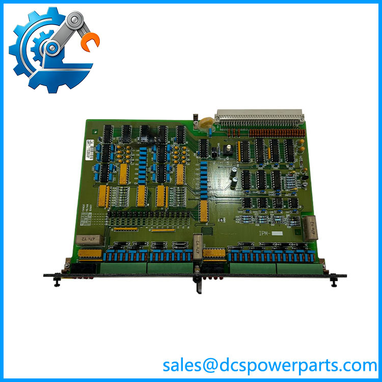
DEIF IPM-1
Key Features and Advantages
One board, sixteen signal types: every channel of IPM-1 can be a contact input, a 0–20 mA loop or a 0–10 V signal, decided in the application program. A cabinet that would otherwise need three different I/O module types for status, commands and analogue values needs one spare part — and on an end-of-life platform, one spare part is the difference between a maintainable plant and a dead one.
Software-defined range, hardware-defined safety: live zero ranges such as 2–10 V and 4–20 mA are set in the CM application, so a transmitter change from 0–10 V to 4–20 mA does not require a new board. The constraint runs the other way too — the module’s channel setup must match the application definition — which is why the configuration record, not the label, is the document that matters at replacement time.
Compact in the rack: 6 TE of width and 0.40 kg, 1.5 W typical. In an 84 TE or 60 TE DGU rack, where slot space is the scarce resource and the SCM-1, CRM-1 and PRM-1 boards all compete for it, a 16-channel input board that draws 1.5 W is a genuinely efficient use of the backplane.
Optical status where it is useful: sixteen numbered LEDs show closed-contact state on binary channels, so a commissioning engineer can confirm a breaker auxiliary or a level switch without a laptop or a control panel page. The LEDs are honest about their own limits — an analogue channel shows nothing, which prevents the false confidence that a permanently lit lamp would give.
Common ground that simplifies cabinets: all COM terminals share the module’s internal ground, so field devices referenced to cabinet 0 V wire directly, without an isolation amplifier per channel. For the typical DGU — where most inputs are contacts and loop-powered transmitters on the same reference — this removes hardware, terminals and failure points.
Analogue front end built for plant signals: 50 Ω on current inputs, 15 kΩ on voltage inputs, Class 1 accuracy to IEC 688 and 0.1 % resolution. That is instrumentation-grade for process values and honest about being nothing more.
Cable supervision on the channels that need it: a 3.3 kΩ shunt across the field device turns a break in the loop into a detectable state instead of a frozen reading, and it is applied by default on the 20 % offset analogue ranges where a lost signal is otherwise indistinguishable from a valid low reading.
Marine-grade approvals that survive audit: 1.0 kV dielectric test to GL, LR and DNV practice, CE marking, and type approval from LR, GL, DNV, ABS, BV, RINA and CNK at system level. On a vessel, that is the paperwork that makes the module acceptable in the switchboard room at all.
Applications
Ship power plants running DELOMATIC 3: the DGU rack in a vessel’s switchboard room, where IPM-1 collects breaker position, generator running and ready signals, fuel and lube-oil pressure switches, cooling-water status and remote control commands from the engine room. This is the largest surviving population of the module, and the reason it is still ordered.
Land-based multi-genset plants and standby power stations: diesel and gas genset installations with DEIF DM-3 control, where the input module carries mains-failure signals, load-shedding commands and the auxiliary contacts that the plant’s own switchgear provides. Plants of this generation are typically kept running well past the OEM’s product life, which is precisely where spare-module supply matters.
Offshore platforms and marine auxiliary systems: installations where the generator control sits inside a certified switchboard and the classification society expects the original type-approved configuration to be preserved. Replacing an with an unapproved substitute changes the approval basis of the whole panel.
CHP and industrial captive power: plants with their own generation and heat recovery, running steam or gas turbine-driven generators under DM-3 supervision, where the input board handles the process permissives that decide whether the machine may start.
Ports, mines and remote industrial grids: isolated distribution systems with several generator sets and no strong utility backup, where status and command inputs are the plant’s only view of what the switchgear is doing.
Retrofit and life extension of existing DGUs: the case that actually drives orders today — a failed channel on a rack that cannot be replaced as a whole, where the correct restores the function and an incorrect 16-channel board from another platform does not.
Related Products
PSM-1 — switch-mode power supply module of the DGU; supplies the through the backplane. CM-2 — the DGU control module; holds the application program that defines each channel’s type and range. OPM-1 — 16-channel relay output module; the output counterpart, with potential-free contacts rated 250 V AC 5 A / 1000 VA. AOM-1 — 8-channel analogue output module; drives speed controllers, AVRs and other analogue references. SCM-1 — synchronising and measuring module for the generator; three-phase measurement, protection, breaker control and synchroniser. SCM-2 — synchronising and measuring module for shaft generators and busbar tie breakers; same family, different application target. CRM-1 — current protection relay module, configured as short-circuit, ground-fault or differential protection. PRM-1 — protective relay module for grid and generator abnormal conditions such as over/under voltage, frequency and negative sequence. CP-1 — control panel; up to three per DGU, with alarm display, parameter access and sixteen instrument outputs. DM-4 / PPM 300 — later DEIF power management platforms; the direction DEIF points customers toward, with no direct one-for-one replacement for DM-3.
Installation and Maintenance
Before installation: confirm the slot is a DGU backplane slot of the correct width for a 6 TE module, and that the rack’s PSM-1 is healthy, since takes its supply from the backplane and has no independent power terminals. Obtain the application program’s channel list before touching the module: each channel’s type — binary, 0–20 mA or 0–10 V — and its live-zero setting live in the CM program, so a board that does not match the definition will appear to work while reporting the wrong engineering value. Verify the field wiring against that list, check that binary inputs are potential-free contacts only, and confirm whether cable supervision is configured, because that determines whether a 3.3 kΩ shunt belongs across the field device.
Wiring and commissioning: use 2.5 mm² single or multi-stranded conductors in the screw terminals, respect the 250 Ω maximum ON resistance for contact detection, and remember that all COM terminals sit on the module’s internal ground — plan the cabinet’s reference before terminating sixteen channels, not after. Bring the rack up with the field circuits isolated, confirm channel-by-channel behaviour through the control panel, then prove the loop-powered analogue channels against a calibrated source. Only the binary channels have front-panel LEDs, so analogue verification has to be done in the application, not at the board.
Maintenance practice: treat channel failures as three separable problems — field circuit, terminal and board — and use the cable supervision state to distinguish an open loop from a valid low reading. Keep a configuration copy of the CM application with the rack’s channel list archived, since it is the only record of what each channel is meant to be. On a platform at end of life, hold spares as with the matching assembly code rather than as a generic input board, and replace one module at a time with the rack powered down, checking the backplane connector and slot guide for damage before seating the replacement.
Warranty and Quality
Each is supplied as the DEIF DELOMATIC 3 input module itself, with the assembly code and revision letter verified against the board marking and the rack’s configuration list checked before dispatch — because on an end-of-life platform the failure mode is not a missing part but a part that fits the slot and does not match the application’s channel definitions. Units are inspected for backplane connector condition, terminal-block integrity, LED and marking legibility, and signs of prior insertion; where a DM-3 rack is available for test, modules are powered through the backplane and checked for channel-by-channel response in binary and analogue configurations, supply current within the 1.5 W typical envelope, and correct behaviour of the contact-detection LEDs. A 12-month repair, replacement or refund commitment applies. Support covers the questions this platform actually raises: how to read a channel list out of the application program, whether a channel is binary or analogue before wiring it, how to apply cable supervision, why an LED is dark when the contact is closed, which module in the DGU the fault really belongs to, and what DEIF’s end-of-life position means for a plant that still depends on DM-3.