Description
Product Overview
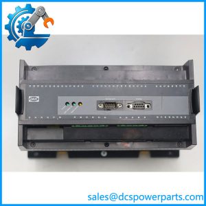
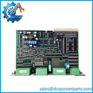
CM-2 is the controller board of a DELOMATIC 3 generator unit. One DGU rack holds exactly one CM, and every other module in that rack — the IPM-1 inputs, the OPM-1 relay outputs, the AOM-1 analogue outputs, the SCM-1 measuring and synchronising board, the CRM-1 and PRM-1 protection modules — is a peripheral to it. The CM runs the application program, coordinates those modules over the backplane communication bus, and presents the DGU as one node on the ARC-network so that generator units can share load and synchronise with each other.
The single most important fact about this board is where its program lives: in two flash PROMs carried on the module. The CM-2 is not a generic CPU that boots from a disk, a card or a network image. Its behaviour in a given plant is a physical property of the chips fitted to it. That is why DEIF publishes a dedicated replacement instruction for the flash PROM set alongside the one for the module itself, and why a CM-2 pulled from another plant is a different controller until the correct PROM pair is transplanted into it — not merely a board that needs commissioning.
Identity is set twice over. The module’s ARC-net node ID comes from a hex switch, offset by a protocol-dependent base value, and the accepted switch range stops at “C”, so positions C through F all resolve to the same address. On a multi-unit plant, that switch is what tells the network and the control panels which generator they are looking at: a CP-1 panel corresponds to the DGU whose node ID matches the number set on the panel, and alarm messages are only displayed on the panels belonging to that machine. A CM replaced without recording the old switch position comes up as the wrong generator — a failure that looks like a network problem and is really an address problem. Switch changes take effect only after the module has been powered down and up again, which has caught out more than one commissioning engineer.
Serial connectivity is not built in. A separate communication module — RS-232, RS-422 or RS-485 — is fitted onto the CM-2 in the rack, takes 24 V DC from screw terminals, weighs 0.5 kg, draws 3 W typical and 5 W maximum, and provides the plant’s link to a higher-level system or a Modbus master. Its single green COM LED encodes four states by lamp behaviour: fast flash for a serial-line failure, slow flash for an ARC-network failure, steady light for healthy communication, and no light at all for a fatal error. Reading the flash rate rather than the colour is the whole diagnostic.
Two LEDs on the CM itself carry the rack’s health. I/O OK stays green while the CM can reach every module the application program expects, at the internal address it expects; if a module is missing at its address or cannot communicate, I/O OK goes dark. LAN OK confirms the ARC-network link. Together they divide the plant’s problems cleanly: LAN OK dark is a network question, I/O OK dark with LAN OK lit is a rack-configuration question, and both dark with a live plant usually means the module is not running at all.
The hardware is modest and marine-rated: 30.5 mm wide, 0.47 kg, supplied from the PSM-1 through the backplane at 1.5 W typical, 1.0 kV dielectric test to GL, LR and DNV practice, IP20 in the rack, and operation to -25 °C with storage to -40 °C. A DELOMATIC system carries CE marking and type approval from LR, GL, DNV, ABS, BV, RINA and CNK — approvals that attach to the system as configured, which is one more reason a substitute controller is not an acceptable repair on a vessel.
DEIF has placed DM-3 at end of life with no direct replacement, so CM-2 survives as an installed-base component: the board that keeps a running DGU alive, and whose value is inseparable from the PROM pair and the node ID it carries.
Technical Specifications
| Parameter | Value |
|---|---|
| Model | CM-2 |
| Manufacturer | DEIF A/S, Denmark |
| Product type | Main control module of a DELOMATIC 3 DGU |
| Quantity per DGU | One; the CM is the rack’s single controller |
| Program storage | Application program held in two flash PROMs on the module |
| Module interface | Backplane communication bus to all modules in the DGU |
| Network identity | ARC-net node ID from a hex switch, accepted positions up to “C”; set by protocol-dependent offset |
| Serial interface | Piggyback communication module, RS-232 / RS-422 / RS-485, 24 V DC, 3 W typical / 5 W maximum, 0.5 kg |
| Supply / consumption | From the PSM-1 via the backplane; 1.5 W typical, 3 W maximum |
| Diagnostics | Green I/O OK: all programmed modules present and communicating; green LAN OK: ARC-net link established |
| Isolation | 1.0 kV, 50 Hz, 1 minute, to GL / LR / DNV practice |
| Dimensions / weight | 30.5 mm wide (6 TE); 0.47 kg |
| Environment / protection | Nominal -10 to +55 °C, operational -25 to +70 °C, storage -40 to +70 °C; climate class HSE per DIN 40040; IP20 in rack |
| Approvals | CE marking; system type approval by LR, GL, DNV, ABS, BV, RINA and CNK |
| Lifecycle status | DM-3 platform at end of life at DEIF; no direct replacement |
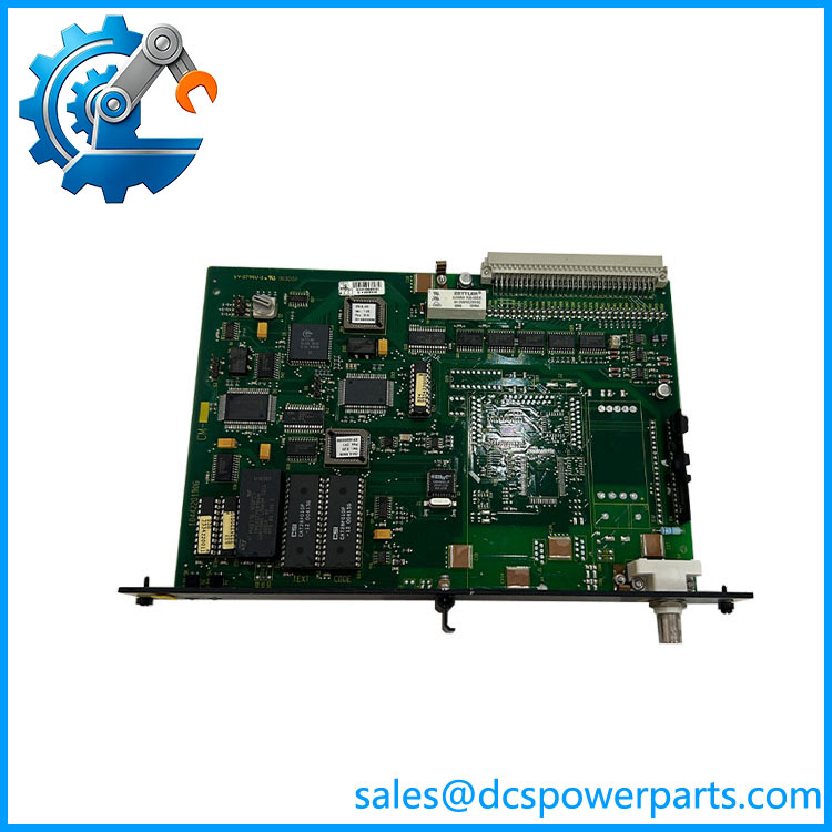
DEIF-CM-2
Key Features and Advantages
The program travels with the board: CM-2 carries the application in two flash PROMs, so the controller’s behaviour is a property of the chips inside it rather than of a file someone hopes still exists on a laptop. In an end-of-life platform, that cuts both ways — it makes a properly transplanted module an exact restoration of the original machine, and it makes a random second-hand CM-2 a controller for somebody else’s plant.
One controller, whole rack: the CM addresses every module at its internal address and reports the result on a single LED. I/O OK therefore validates the entire rack configuration — module types, slot positions, application expectations — in one indication, which is faster and more honest than checking each board’s LEDs in turn.
Network identity you can set and read: the ARC-net node ID hex switch ties the DGU to its number, its control panels and its share of the load-sharing network. On a plant with several machines, that is the difference between a synchronising system and a set of controllers that all believe they are generator one.
Diagnostics by lamp behaviour, not by guesswork: I/O OK for the rack, LAN OK for the network, and the piggyback communication module’s COM LED distinguishing serial-line failure (fast flash) from ARC-network failure (slow flash) from fatal error (dark). Three indicators resolve nearly every first-line fault without a laptop.
Serial connectivity that can be changed without changing the controller: RS-232, RS-422 and RS-485 variants mount on the same CM-2, so a plant that migrates its supervisory link does not need a new controller — only the 0.5 kg communication module and the corresponding wiring, with 120 Ω termination on the RS-485 pair.
Marine-grade electrical and environmental margins: 1.0 kV dielectric test to classification-society practice, operation to -25 °C, HSE climate class, self-extinguishing plastics to UL94-V0, IP20 in the rack. These are the numbers that let the module live in a switchboard room rather than a clean room.
Modest load on a shared supply: 1.5 W typical through the backplane means a fully loaded DGU rack stays within the PSM-1’s budget, and a CM fault does not masquerade as a power-supply problem.
A documented replacement path, even at end of life: DEIF publishes module-level and PROM-level replacement instructions for DM-3, which is what makes a controlled swap possible on a platform the OEM no longer builds.
Applications
Ship power plants with several generator units: up to eight DGUs and their control panels on one ARC-network, where each CM-2 holds the node identity of its machine and shares load with the others. This is the archetypal DELOMATIC 3 installation and the largest surviving population of the module.
Land-based multi-genset and standby stations: diesel and gas plants where the CM executes start sequences, synchronising, load sharing and load-dependent start/stop, and where the failure of one controller must not be confused with a failure of the plant’s switchgear.
Island and isolated grid operation: port, mine, factory and remote-community systems running without a strong utility, where the CM’s load-sharing and load-shedding behaviour is what keeps frequency inside limits when a large consumer starts or a generator trips.
CHP and industrial captive generation: plants with steam or gas turbine generators under DM-3 supervision, where the CM-2 coordinates the protection modules and executes the permissives that decide whether a machine may be paralleled.
Marine auxiliary and offshore installations: certified switchboards where the approved configuration is part of the vessel’s or platform’s compliance basis, and where a controller swap must preserve the type-approved arrangement rather than approximate it.
Life extension and emergency repair of existing DGUs: the case that drives orders today — a controller that will not boot, or a rack that reports I/O OK dark after a module change, where the answer is a CM-2 with the correct PROM pair and the original node-ID setting, not the nearest available controller board.
Related Products
PSM-1 — switch-mode power supply module; feeds the CM-2 and the rest of the rack through the backplane. IPM-1 — 16-channel universal input module; the field-signal front end the CM addresses over the backplane bus. OPM-1 — 16-channel relay output module; the CM’s means of driving contactors, alarms and breaker commands. AOM-1 — 8-channel analogue output module; supplies speed and voltage references to governors and AVRs. SCM-1 — synchronising and measuring module for the generator; three-phase measurement, protection, breaker control and synchroniser. SCM-2 — synchronising and measuring module for shaft generators and busbar tie breakers. CRM-1 — current protection relay module, configured for short-circuit, ground-fault or differential protection. PRM-1 — protective relay module for voltage, frequency and negative-sequence conditions. CP-1 — control panel; up to three per DGU, addressed to the DGU whose node ID it matches. RS-232 / RS-422 / RS-485 communication module — piggyback module fitted onto the CM-2 to give the DGU a serial link to a higher-level system. DM-4 / PPM 300 — later DEIF power management platforms; the migration direction, with no direct one-for-one replacement for DM-3.
Installation and Maintenance
Before installation: establish what the rack documents — a CM-2 label is not sufficient evidence, because the controller’s identity is the combination of the board, the two flash PROMs on it and the node-ID switch setting. Obtain the original PROM pair or a verified copy from the machine being repaired, record the hex switch position and the protocol-dependent offset before removing anything, and note which communication module — RS-232, RS-422 or RS-485 — is fitted, since that module is what carries the plant’s supervisory link. Check that the rack’s PSM-1 is healthy and that the backplane connector and slot guide are undamaged before seating the replacement. Power the rack down for the swap, and remember that dip and hex switch changes only take effect after a power cycle.
Commissioning: power up and watch the two LEDs in order — I/O OK green means the CM has found every module the application program expects at the expected address; LAN OK green means the ARC-network link is up. Then confirm on the CP-1 that the panel addresses the correct generator, verify load sharing and synchronising behaviour with the other units, and prove the serial link at whatever protocol the communication module provides, respecting the 120 Ω termination required on an RS-485 pair.
Maintenance practice: triage by LED before replacing hardware. I/O OK dark with LAN OK lit points to a module missing or mismatched at its address — usually a changed board type in the rack, not a failed controller. LAN OK dark points to the network: duplicate node IDs, a broken coaxial segment, missing end terminators or disturbed ferrite cores. On the communication module, a fast COM flash is a serial-line fault and a slow flash is an ARC-network fault; a dark LED means the module itself is not running. Keep the PROM pair and the node-ID record with the rack’s documentation, treat them as the asset they are, and never discard a removed CM-2 before its PROMs have been read and archived.
Warranty and Quality
Each CM-2 is supplied as the DEIF DELOMATIC 3 control module with its program situation established before dispatch — PROM pair present, readable and identified, or explicitly declared absent — and with the node-ID and communication-module requirements confirmed against the buyer’s rack, because a controller without the right program image is a board that boots into the wrong machine. Units are inspected for backplane connector condition, PROM socket and chip condition, switch and label legibility, and signs of prior removal or rework; where a DM-3 rack is available for test, modules are powered through the backplane and checked for boot behaviour, I/O OK and LAN OK indications, address recognition against a known module set, and serial communication through the fitted communication module. A 12-month repair, replacement or refund commitment applies. Support covers the questions this platform actually raises: how to identify which PROM set a rack needs, how to transplant and archive a program, how to set and time the node ID correctly, how to read I/O OK and LAN OK as separate answers, how to interpret COM flash rates, and what DEIF’s end-of-life position means for a vessel or plant that still runs on DM-3.