Description
Product Overview
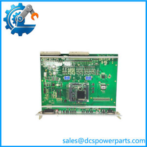
I/OBE2 12004-104-00 V1.0.0 is the least glamorous card in a control cabinet and the one that determines whether the cabinet’s architecture holds together. It is not an I/O module. It has no field terminals, no analogue channels and no front-panel network port, because its entire job is to carry the rack’s own I/O bus from the controller backplane out to further I/O segments — electrically continuing a bus that would otherwise stop at the end of the chassis. Everything the plant actually measures and drives still terminates on the I/O cards; this board only decides how far that bus reaches and how cleanly it arrives.
The number explains the family without needing a catalogue. 12004-102-01 is the VPS board, 12004-103-01 is I/OBUS2, the I/O bus interface card, and 12004-104-00 is I/OBE2. Three consecutive function codes in one product block, distinguished by the third field, with a two-digit variant field behind it. Reading the block as a sequence is the single most useful thing a maintenance engineer can do with these numbers, because it places the extender next to the interface it serves: I/OBUS2 is the card that drives the bus, and I/OBE2 is the card that continues it. A plant holding one without the other has half of a bus architecture.
The V1.0.0 suffix is the part most often misread. It is a revision marker — the version printed on the board, the one a spare must be matched against — and the market cannot agree on whether it names a firmware build or a hardware issue. One seller calls V1.0.0 the initial firmware and says later V1.1 and V1.2 releases fixed communication faults on unchanged hardware; another describes the same card as a hardware-level extender with no field-updatable firmware at all. Both cannot be right, and neither is authoritative. What is certain is the consequence: in a bus-extension role the two ends of the link must be revision-compatible, so a V1.0.0 card dropped into a rack whose other bus cards run a later revision is a compatibility question to be answered before the outage, not discovered during it.
The descriptions attached to this part in the market are, frankly, a demonstration of why the number should be trusted and the prose should not. One seller files it as a pulse-output module generating 100 kHz CW/CCW pulse trains for stepper and servo motors, with PCI/PCI-X expansion slots and USB connectivity — a description that would require the card to be a plug-in PC card, which it is not. Another sells it as a 16-input/8-output DIN-rail module with RS-485 and CANopen. A third gives it 200 × 150 × 50 mm, 1.2 kg, Ethernet and RS-232 and calls it a PLC component. And the same seller that describes I/OBUS2 as an iLOCK railway interlocking card on one page describes that identical part number as a generic DCS analogue/digital interface with 4–20 mA inputs on another. One part number, two identities, one website.
What survives all of that is the architecture. The card is a plug-in board for a 19-inch ALSTOM rack, powered from the backplane, secured with captive screws, carrying no field wiring, and marked with a revision. It exists so that an installed cabinet can reach I/O that sits beyond the chassis without redesigning the field wiring or the application software — which is precisely the kind of card a brownfield plant needs when a rack is being extended rather than replaced.
The platform attribution is the remaining loose end, and it should be stated as loose. Some sellers place this family in ALSPA-generation power plant DCS racks — turbine governor cabinets, boiler and balance-of-plant I/O — while another places the same block in Alstom’s iLOCK computer-based interlocking for railways. The rack-architecture facts hold in either case; which plant type the card was built for is not settled in the public record. A buyer with a cabinet in front of them can settle it in a minute by looking at what the neighbouring cards are.
Technical Specifications
| Parameter | Value |
|---|---|
| Designation | I/OBE2 (written with the slash; sellers commonly drop it to “IOBE2”) |
| Order number | 12004-104-00 |
| Version / revision suffix | V1.0.0 (marker on the board; firmware vs hardware issue not published) |
| Manufacturer | Alstom (legacy control rack product line; power automation transferred to GE, 2015) |
| Product type | I/O bus extender / backplane interface board — no field I/O |
| Family position | Third function code in the 12004-10x block, beside 12004-102-01 VPS and I/OBUS2 12004-103-01 |
| Rack format | Plug-in card for 19-inch ALSTOM chassis, card guides, captive screws, backplane connector |
| Power supply | From the rack backplane; no external supply input on the board |
| Field termination | None — no front-panel field wiring, no front Ethernet or serial port |
| Bus function | Proprietary ALSTOM rack I/O bus extension to downstream/remote I/O segments |
| Operating environment | Ventilated control cabinet, typically 0 to +55 °C; IP20 (cabinet interior only) |
| Replacement method | Cold swap with rack powered down; captive fasteners, card-edge guides |
| Lifecycle status | No official end-of-life notice located; supply is dismantled and refurbished stock |
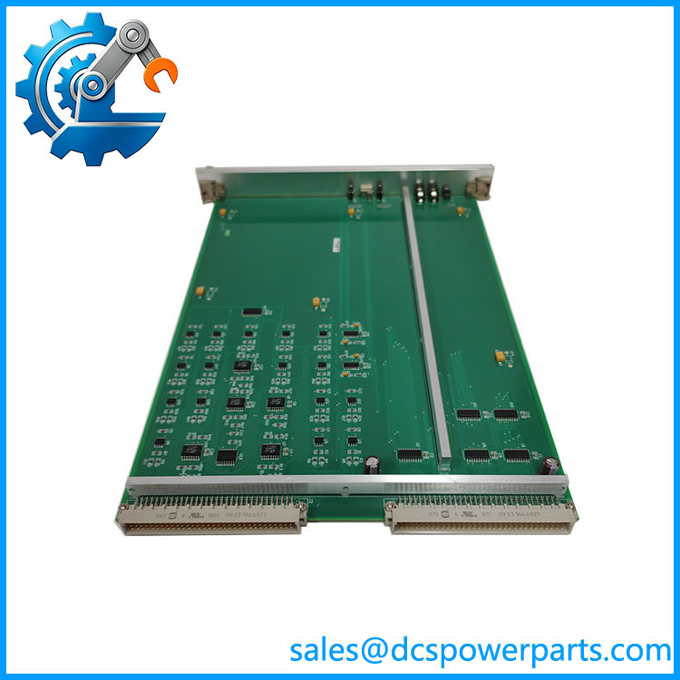
IOBE2 12004-104-00 V1.0.0
Key Features and Advantages
Bus extension rather than signal conversion: the card does not translate, scale or isolate anything — it continues the rack’s own deterministic I/O bus. That means no protocol gateway, no address translation table and no software change when a rack is extended, which is exactly what a phased migration needs.
Position in a readable numbering block: sitting at function code 104 immediately after the bus interface at 103 and the VPS board at 102, I/OBE2 can be placed in the architecture from the number alone. In a plant whose drawings are decades old, that is a genuine diagnostic asset.
No field wiring on the board: every terminal in the cabinet stays where it is. A replacement therefore carries no rewiring risk, no marshalling error and no loop-check requirement — the intervention is confined to one slot.
Backplane-powered operation: there is no separate supply to wire, fuse or fail. The board inherits the rack’s power architecture, which also means a supply fault presents as a bus fault and should be investigated at the rack, not at the card.
Revision-marked hardware for spare control: V1.0.0 on the label lets a storeman match a spare against the site standard before it goes in a flight bag. On a bus card, a revision mismatch is a compatibility question, and the label is the only place that question can be answered cheaply.
Cold-swap discipline that protects the backplane: captive screws and card guides make a planned replacement a ten-minute operation, provided the rack is down. The same construction makes hot insertion a bad idea, and the board should be treated as such.
Honest limits: no OEM datasheet exists for this card, the platform attribution is contested between ALSPA power racks and iLOCK rail interlocking, and the market descriptions for it are mutually exclusive. Every specification above is architectural or verifiable from the board itself; nothing has been invented to fill a table.
Applications
Turbine and balance-of-plant cabinets: in legacy ALSTOM racks used for governor and auxiliary control, I/OBE2 is the card that lets a chassis reach I/O physically located elsewhere in the cabinet row — feedwater, condensate, auxiliary contactors and status signals that sit beyond the controller’s own frame.
I/O segment extension in brownfield plants: where a control cabinet is being extended rather than replaced, the extender is the alternative to re-engineering the field wiring. The bus is continued, the existing I/O cards stay in place, and the application software sees the same addresses it always did.
Phased migration and life extension: plants that cannot justify a full control-system replacement typically replace failed cards and extend existing segments. A working I/ 12004-104-00 keeps the architecture intact through those phases, which is the difference between a migration programme and an emergency.
Spare holding for obsolete racks: with factory supply gone and refurbished stock the only channel, the bus card is worth holding deliberately. A rack that loses its extender loses its remote I/O segment even though every I/O card in it is healthy.
Remote and distributed I/O segments: where the installed architecture distributes I/O across cabinets rather than concentrating it in one, the extender is the physical link that makes the distribution work with predictable latency.
Where it does not fit: applications described in terms of pulse trains, stepper or servo motor drives, PCI expansion slots, DIN-rail mounting, or 4–20 mA field channels. This board has no field I/O and does not mount on a DIN rail.
Related Products
I/OBUS2 12004-103-01 — the I/O bus interface card of the same block; it drives the bus that extends, and the two are normally specified together. 12004-102-01 VPS (VER.C) — voltage/power supply board of the same 12004-series rack; the block’s first function code. CMP1838 (TRVCO62345000 / CP00005202) — ALSPA-generation rack control board, the controller the bus ultimately serves. DSI1817 (TRVC062335000 / CP00003934) — rack I/O board of the same cabinet generation; the type of card whose segment the extender carries. STO1726KO1 (4022.437.1856) — digital input/output board in the same cabinets, mated through the marshalling layer. ECPU_1 (N895600512D / N895600051C / N895600200Q) — central processor board of the legacy ALSTOM/AREVA rack family. ALSTOM 12004-series rack chassis and backplane segments — the mechanical and bus hardware both I/OBUS2 and depend on; slot keying and backplane revision determine whether a card can be fitted at all.
Installation and Maintenance
Before installation: establish the site standard first. Record the version marking on the card being removed and on the other bus cards in the rack, and confirm that a V1.0.0 replacement matches it — on a bus extender a revision mismatch is a compatibility decision, not a detail. Check the slot keying and the backplane connector for bent pins before inserting anything, verify that the rack’s addressing or slot configuration matches the site drawing, and take a photograph of the populated rack so the card’s position is recorded independently of a label. De-energise the rack completely: this generation has no hot-swap provision, and inserting a bus card into a live backplane risks both the card and the segment it serves.
Installation: work grounded, slide the card along its guides until the backplane connector seats fully, then tighten the captive screws evenly — a partially seated bus card produces intermittent faults across an entire I/O segment and is routinely misdiagnosed as multiple card failures. On power-up, confirm the rack reaches a stable state before trusting any I/O reading, and check bus status indication at both the interface card and the extender.
Maintenance: treat cabinet cooling as part of the bus system — an overheated rack produces bus errors that look like card faults. Inspect backplane connectors for oxidation at each outage, clean with dry air rather than solvents, and do not re-seat working cards as routine practice; the connectors are no longer in production. Keep one verified I/ 12004-104-00 V1.0.0 spare per rack architecture in use, labelled with its revision, because losing this card takes an entire I/O segment offline while every I/O card in it remains healthy.
Warranty and Quality
Every I/ 12004-104-00 V1.0.0 board is supplied as an Alstom 12004-series rack I/O bus extender and is identified by order number and version marking, with the revision recorded on the delivery documentation so it can be matched against the site standard before installation. Units are inspected for backplane connector condition and pin integrity, card-edge and guide wear, captive screw function, PCB damage, rework evidence and corrosion, and for the legibility of the version label; where a suitable chassis is available the card is checked for stable bus operation in a powered rack. No channel count, processor type or field-I/O specification is asserted, because this board has none and the figures published by resellers describe different products. A 12-month repair, replacement or refund commitment applies. Technical support covers what this part actually requires: placing correctly against I/ 12004-103-01 in the 12004-10x block, explaining why V1.0.0 is a revision to be matched rather than a feature to be upgraded, and why a bus extender with no field terminals is the card whose failure is most often blamed on the I/O cards around it.