Description
Product Overview
The Allied Telesis AT-2712FX/MT-SB-901 990-004100-901 is a legacy fiber Ethernet networking component intended to provide optical connectivity within compatible network equipment and industrial communication systems. Available references consistently associate the part number with the AT-2712FX/MT-SB-901 designation and identify its interface as fiber optic, with multimode fiber support reported for this particular configuration.
The Allied Telesis AT-2712FX/MT-SB-901 990-004100-901 is useful in installations where copper cabling is unsuitable because of distance, electrical noise, or the need for galvanic isolation. In an industrial automation network, an optical Ethernet connection can be positioned between control cabinets, network aggregation equipment, or other electrically separated sections of a plant communication infrastructure. The Allied Telesis AT-2712FX/MT-SB-901 990-004100-901 should, however, be matched against the host equipment and optical transceiver requirements rather than purchased solely on the AT-2712FX family name.
There is a procurement caveat worth emphasizing. Publicly indexed information for this exact suffix is sparse, and some secondary product pages combine specifications from unrelated Allied Telesis equipment. One source claims support for IEEE 802.3, 802.3u, and 802.3z, while another assigns a 12-port copper configuration that conflicts with the fiber-adapter identification. For a replacement project, the physical label, connector arrangement, PCB revision, optical interface, and host assembly documentation should take precedence over generic web specifications.
For lifecycle support, this module is best treated as a legacy fiber-network replacement component. Before commissioning, verify optical wavelength, fiber type, link speed, connector style, host compatibility, and network configuration. Those checks are inexpensive compared with troubleshooting a communication fault caused by a superficially similar module.
Key Technical Specifications
| Parameter | Value |
|---|---|
| Product Model | AT-2712FX/MT-SB-901 |
| Part Number | 990-004100-901 |
| Manufacturer | Allied Telesis |
| Product Type | Fiber Ethernet Network Interface Module |
| Network Technology | Ethernet / Fast Ethernet family |
| Physical Interface | Fiber optic |
| Fiber Type | Multimode fiber reported |
| Intended Function | Optical Ethernet connectivity |
| Application | Industrial communication, enterprise networking, legacy automation networks |
| Installation | Host-equipment dependent |
| IEEE Standards | IEEE 802.3 / 802.3u reported in available references |
| Optical Speed | Exact configuration requires verification |
| Optical Wavelength | Requires verification from hardware label/documentation |
| Connector Type | Requires verification |
| Power Requirement | Host-system dependent |
| Operating Temperature | Exact rating requires verification |
| Part Identification | AT-2712FX/MT-SB-901 / 990-004100-901 |
Technical caution: I would not publish a fixed wavelength, connector type, temperature range, port count, or switching capacity for this exact part without a primary datasheet or clear board-level identification. Available secondary sources conflict on these parameters.
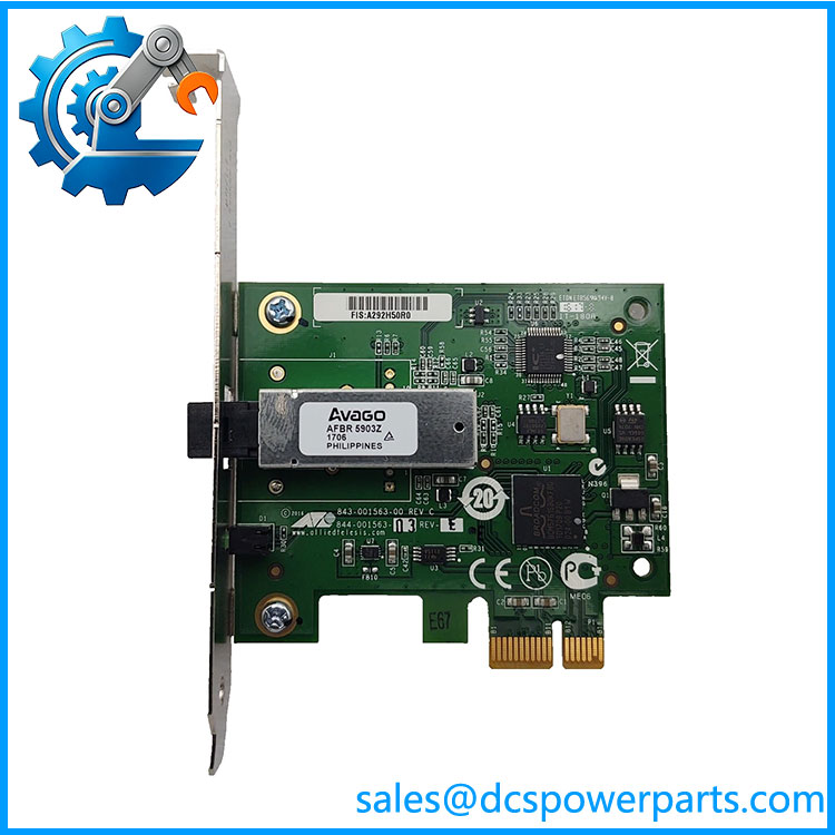
AT-2712FXMT-SB-901
Related Products
- Allied Telesis AT-2712FX/MT-SB-901 — The same core model designation without the separate part-number presentation. Useful when searching legacy documentation or installed-equipment labels.
- Allied Telesis AT-2712FX Series — Related fiber Ethernet hardware family. Configuration differences must be checked before substitution because optical interfaces and mounting arrangements can vary.
- Allied Telesis AT-210T — A different Allied Telesis Ethernet interface product appearing in the same legacy equipment inventories. It should be considered an alternative networking component only after electrical and protocol requirements are established.
- Allied Telesis Fiber Ethernet Equipment — Related optical networking hardware can provide similar communication functions, but a replacement must match fiber type, optical characteristics, speed, connector, and host interface.
- Multimode Fiber Ethernet Transceiver — A complementary component where the installed system uses replaceable optical transceiver hardware. Exact wavelength and connector compatibility must be confirmed first.
- Industrial Ethernet Switch — A functional alternative for a redesigned network segment, but not a direct replacement for this specific interface module where the original hardware is part of a larger host assembly.
Frequently Asked Questions
1. What is the Allied Telesis AT-2712FX/MT-SB-901 990-004100-901 used for?
The available identification data points to a fiber Ethernet network interface designed for optical communication. It is particularly relevant to older network installations where multimode fiber is used between equipment.
It should not be classified as a PLC CPU, DCS I/O module, or standalone process controller.
2. Can I replace AT-2712FX/MT-SB-901 with another Ethernet module?
Not without checking the physical and communication interface.
Verify:
- Fiber type
- Optical wavelength
- Link speed
- Connector type
- Host slot/interface
- Electrical requirements
- Network protocol requirements
A generic Ethernet module may communicate at the protocol level but still be mechanically or optically incompatible.
3. Does the AT-2712FX/MT-SB-901 support Gigabit Ethernet?
I would not confirm Gigabit support for this exact 990-004100-901 configuration based on the available evidence. One secondary source claims IEEE 802.3z support, but other published information conflicts with its hardware description.
For procurement, use the physical module marking and original system documentation to establish the actual link speed.
4. Can I hot-swap this module?
Do not assume hot-swap capability.
The safe procedure depends on whether the AT-2712FX/MT-SB-901 is installed as a standalone network adapter, a host-mounted module, or part of a larger industrial assembly. If the host equipment does not explicitly support live replacement, power down and isolate the equipment before removing the module.
5. What should I check when a replacement shows no optical link?
Start at the physical layer:
- Confirm the fiber is multimode if required.
- Check TX/RX polarity.
- Inspect the optical connectors.
- Confirm both ends use compatible optical characteristics.
- Verify link-speed settings.
- Check host-module recognition.
- Review network diagnostics.
Optical link failures are often caused by fiber polarity, contamination, or incompatible optical parameters rather than the Ethernet protocol itself.
6. How can I verify a New Surplus AT-2712FX/MT-SB-901 990-004100-901?
For this part number, inspection should be more rigorous because public specifications are inconsistent.
Request or verify:
- Exact AT-2712FX/MT-SB-901 label
- 990-004100-901 part number
- PCB revision
- Optical connector configuration
- Host/interface connector
- Original packaging where available
- Power-up test
- Optical link test
- Network communication test
A photograph of the actual label and connector side is particularly useful when distinguishing this module from other AT-2712FX variants.
7. Is this suitable for a DCS/PLC legacy replacement project?
Potentially, yes, if the existing control network uses this specific optical interface. It is a communication component, not a controller or I/O replacement.
For a DCS/PLC network upgrade, verify the complete communication path—host hardware, optical interface, fiber characteristics, Ethernet speed, network topology, and software configuration—before approving the replacement.