Description
Product overview
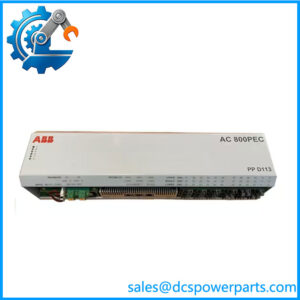
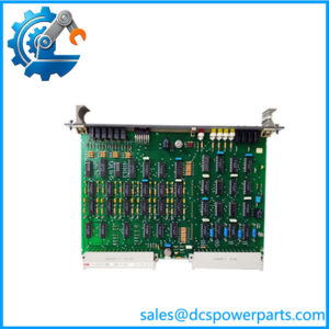
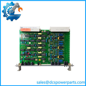
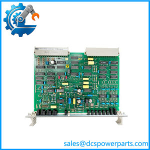
The ABB Bailey IPMON01 Power Monitor Module is a monitoring component for the INFI 90 OPEN Modular Power System II and related Harmony power-system configurations. Its job is to supervise the condition of the control system’s power infrastructure and report abnormal states. Unlike the IPSYS01 system power module or IPFLD-series field power modules, the IPMON01 does not generate the main DC power rails. It monitors bus voltages, power-module status, auxiliary power inputs, cabinet temperature signals, and cooling-fan status so maintenance personnel can identify power-related problems before they disrupt control-system operation.

ABB Library
+1
In a configured system, the IPMON01 monitors the 5 VDC, +15 VDC, −15 VDC, and 25.5 VDC buses, along with applicable 48 VDC and 125 VDC I/O buses and selected auxiliary supplies. It accepts two logic-level status inputs, two cabinet-temperature monitor inputs, and two fan-status inputs. Its outputs include bus, power, and I/O alarms, a power-fail interrupt (PFI), and a system-status signal for supported plant communication networks. The front panel provides status indicators and test points for checking key DC bus voltages.
快速时间在线
+1
When sourcing the ABB Bailey IPMON01, verify the existing module designation and the installed power-system generation. This is important because ABB documentation distinguishes the Modular Power System II from earlier Network 90 and INFI 90 power systems; components from those earlier systems are not automatically interchangeable with MPS II components. Before replacement, document the chassis type, wiring and status-input configuration, auxiliary-voltage selection, and PFI latching behavior. A matching model number should be paired with a condition assessment and appropriate functional checks, not treated as proof that a used or surplus module is ready for service.
Product introduction
The IPMON01 is installed in the designated center slot of the compatible power-module chassis. It provides monitoring and alarm functions for the power system as a whole, while individual system and field power modules supply the required DC outputs. The module’s status inputs and alarm outputs help distinguish a power-system fault from a problem elsewhere in the DCS. Its front-panel test points support direct checks of selected bus voltages during maintenance and troubleshooting.
The correct replacement process begins with the power chassis model and the existing module’s configuration. Confirm the selected auxiliary input ranges, logic-contact settings, cabinet-temperature monitoring settings, fan-status connections, and PFI behavior against the applicable installation manual. After installation, verify the indicated power status and alarm signals and confirm that the control system receives the expected power-system status. Follow site isolation and electrical-safety procedures before removing or installing hardware.
Key technical specifications
| Parameter | Specification |
|---|---|
| Manufacturer | ABB Bailey Controls |
| Model | IPMON01 |
| Product type | Power Monitor Module |
| System family | INFI 90 OPEN / Harmony Modular Power System II |
| Input power | 120 VAC, 240 VAC, or 125 VDC |
| Input current | 0.3 A at 120 VAC; 0.2 A at 240 VAC or 125 VDC |
| System bus monitoring | 5 VDC, +15 VDC, −15 VDC |
| I/O bus monitoring | 25.5 VDC, 48 VDC, and 125 VDC, as applicable |
| Auxiliary inputs | Two selectable inputs for 24, 48, or 125 VDC external sources |
| Logic status inputs | Two; configurable for normally open or normally closed contacts |
| Temperature inputs | Two cabinet-temperature monitor inputs |
| Fan status inputs | Two |
| Alarm outputs | Bus alarm, power alarm, and I/O alarm; isolated outputs |
| Other status outputs | Power-fail interrupt and system-status output |
| Front-panel indicators | Three red/green LEDs plus eight status-input LEDs |
| Test points | Six, including selected DC buses and system/I/O common |
| Weight | 0.71 kg |
| Dimensions (H × W × D) | 218.4 × 35.56 × 401.32 mm, including handle |
| Operating environment | Refer to the applicable MPS II documentation and installed enclosure requirements |
Specification note: The listed dimensions and weight are from ABB’s MPS II datasheet. Bus-voltage trip thresholds depend on the monitored rail and auxiliary-input configuration; consult the detailed manual before using trip values for commissioning or acceptance testing.
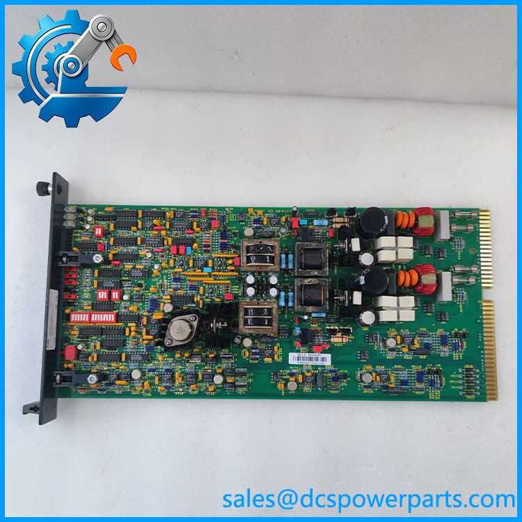
IPMON01
Related products
- IPSYS01 — System Power Module: Supplies the principal system DC rails and 25.5 VDC I/O power in the applicable MPS II configuration.
- IPFLD01 / IPFLD24 — Field Power Modules: Supply 25.5 VDC field I/O power at different rated capacities.
- IPFLD48 — 48 VDC Field Power Module: Supplies a 48 VDC field-power bus in supported configurations.
- IPFLD125 — 125 VDC Field Power Module: Supplies a 125 VDC field-power bus in supported configurations.
- IPCHS01 / IPCHS02 — Power Module Chassis: Provide the chassis and bus infrastructure for compatible power-system modules.
- IPFAN14 — Power System Fan: Provides cooling for the applicable power-system assembly.
These components have different functions and are not direct substitutes for the . Compatibility should be confirmed against the exact power-system generation and chassis model.
Frequently asked questions
Q1: What does the ABB Bailey do?
It monitors system and I/O bus voltages, power-module status, auxiliary supplies, cabinet-temperature signals, fan status, and configured status inputs. It reports abnormal conditions through its alarm and status outputs.
Q2: Does supply power to the DCS?
No. It monitors the power system. Modules such as IPSYS01 and the IPFLD series provide the DC outputs.
Q3: Which power systems use ?
ABB documents it as part of the Modular Power System II used with Harmony equipment and the INFI 90 OPEN MPS II configuration. Confirm the installed chassis and system generation before ordering.
Q4: What input power does require?
ABB lists 120 VAC, 240 VAC, or 125 VDC input configurations. The documented input current is 0.3 A at 120 VAC and 0.2 A at 240 VAC or 125 VDC. Verify the applicable wiring and input arrangement before installation.
Q5: Can be used in an older Network 90 power system?
Do not assume so. ABB’s MPS II documentation explicitly distinguishes the MPS II from earlier Network 90 and INFI 90 OPEN power systems and states that their components are not interchangeable with MPS II components. Confirm the exact system generation.
Q6: What should be checked before installing a replacement?
Check the module label, chassis model, auxiliary-voltage selections, status-input wiring, temperature and fan monitoring connections, and PFI configuration. After installation, verify power indications and alarm reporting against the system manual.
Q7: What evidence should a supplier provide?
Request clear photographs of the module label and connectors, a written condition declaration, available inspection or functional-test records, warranty terms, and confirmation that the unit matches the installed system configuration. Do not assume that “new” or “tested” means the same thing across suppliers.
Procurement recommendation
For ABB Bailey , the most important procurement check is compatibility with the installed Modular Power System II or INFI 90 OPEN power configuration. Provide the supplier with the existing module designation, chassis model, and any available system documentation.
Before purchase, confirm:
- Exact identification and physical condition.
- Whether the unit is new, unused surplus, refurbished, or used.
- Whether inspection or functional testing was performed and whether records are available.
- Compatibility with the existing power chassis and configured monitoring inputs.
- Stock status, dispatch estimate, warranty coverage, and return terms.
For a live DCS installation, do not treat a replacement as verified solely because its label reads . Confirm the power-system generation and the required monitoring behavior before returning the equipment to service.