Description
Product Overview
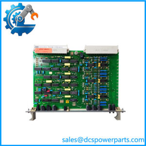
500PSM03A 1MRB150038R1 is the 100 W member of this family’s supply pair, and unlike the smaller 500PSM02 its documentation opens up rather than merely confirming. ABB’s operating instructions for the COM581 gateway — 1MRB520267-Uen, Rev. D — describe it as a DC/DC converter with electrical insulation between input and output, and then list what no resale page does: four regulated rails at +3.3 V (8 A), +5 V (16 A), +12 V (3 A) and −12 V (0.5 A), with the tolerances of all four continuously monitored. That list is the reason this module is worth understanding rather than just replacing: it is not a single-voltage supply, it is the source of every rail the rack’s logic, analog front ends and communication boards run on.
The input window reconciles two ABB documents that looked, at first glance, like two different specifications. The REC 580 terminal manual states 36 to 312 V DC; the COM581 manual states the same figure and then explains it — 48 V −25 % to 250 V +25 %. One number, two ways of writing it, and the earlier appearance of a discrepancy was only a difference in presentation. That window is deliberate: substation auxiliary batteries are 48 V, 110 V, 220 V or 250 V depending on the installation’s age and country, and a supply card that accepts all of them without a selector is a supply card a utility can hold as a single spare across a mixed fleet.
The electrical details that decide whether an installation is safe are all in the COM581 document. The input is protected by a 10 A / 250 V slow fuse; the inrush current on energising is limited to 10 A; and an external miniature circuit-breaker of type S282 UC-K 6 is recommended upstream. Those three figures answer the question a panel builder actually asks — what to put in front of the card — and none of them appears in any of the listings that sell it. Equally specific is the rail budget: the individual maxima of the four outputs sum well above 100 W, so no installation can load all four simultaneously to their limits, and the total remains the binding constraint. A rack designed against “16 A at 5 V” alone will be designed wrong.
Redundancy, again, is an arrangement rather than a property of the card, but here the arrangement differs from the terminal’s. In the COM581 rack, two 500PSM03A units in the paired supply slots provide redundant parallel supplies through a load-balancing circuit, and a yellow LED reports when one of the pair has failed, tied to the unit’s warning signalling relay. In the REC 580 terminal, the second supply goes in the extra position that only the 500CRB01 backplane provides. Two products, two mechanisms, one card — which is why the same module turns up in both manuals and in both sets of slot tables.
The card also carries a warning that is more important than any of its ratings. The on/off switch on its front panel does not isolate its input from the supply; putting the switch in the off position leaves the unit on standby with its input still live. To remove or insert a supply unit, the supply must be switched off at the source and the green supply connector withdrawn, and other modules may only be inserted or withdrawn while the supply units are switched off. Every ABB page about this family repeats that instruction in capitals, and every resale page omits it.
Two naming details complete the identity. ABB’s own ordering list prints 500PSM03 1MRB150038 R0001, with no trailing letter, while the trade overwhelmingly prints 500PSM03A 1MRB150038R1 — the same module, with an A appended and the release shortened from four digits to one. The order code is the anchor in either form. And two further internal strings appear beside it on some listings, 894-030375D and 136-011100H, which belong to the assembly or drawing layer rather than to ordering and are best treated as label data to be matched, not as part numbers.
The trade’s platform claims for this card are as wrong as they are for its siblings: an AC500 PLC supply, a component of legacy INFI 90 and Symphony Plus DCS racks, a main control board supporting communication protocols. ABB’s own documentation places it in a bay control terminal and a substation gateway, and names it plainly as a power supply unit.
Technical Specifications
| Parameter | Value |
|---|---|
| Module designation | 500PSM03A in trade use; ABB ordering list prints 500PSM03 |
| Order code | 1MRB150038R1; official list form 1MRB150038 R0001 |
| Module type | Power supply unit, DC/DC converter with electrical insulation between input and output |
| Output power | 100 W maximum |
| Output rails | +3.3 V DC (8 A), +5 V DC (16 A), +12 V DC (3 A), −12 V DC (0.5 A); individual maxima, not simultaneous |
| Output monitoring | Tolerances of the output voltages continuously monitored; green LED extinguished on short-circuit or overload |
| Input voltage | 36 V DC to 312 V DC — that is 48 V −25 % to 250 V +25 % — without any switching of ranges |
| Input protection | 10 A / 250 V slow fuse; inrush current limited to 10 A; external m.c.b. type S282 UC-K 6 recommended |
| Input power | ≤140 W at full load and 48 V input (REC 580 data) |
| Casing internal loss | Maximum 10 W |
| Bridging time | >50 ms voltage interruption (REC 580 data) |
| Redundancy — COM581 | Two units in paired supply slots, redundant parallel operation via load-balancing circuit; yellow LED plus warning relay on partner failure |
| Redundancy — REC 580 | Second unit in the extra supply position, 500CRB01 backplane only |
| Slot allocation (COM581) | Supply slots 1–2 and 20–21; CPU slots 3, 5 … 19; star coupler slots 4, 6 … 18; 21 slots total |
| Front panel | On/off switch that does not isolate the input; green supply connector must be withdrawn for removal |
| Sibling | 500PSM02 — 60 W, order code 1MRB150015R1, same input window, one supply position in 500CRB02 |
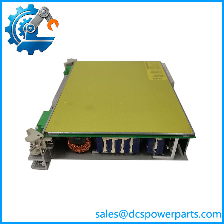
500PSM03a 1MRB150038R1
Key Features and Advantages
Four rails from one card: +3.3 V, +5 V, +12 V and −12 V at 8 A, 16 A, 3 A and 0.5 A respectively, all continuously monitored — the reason the rack’s logic, analog and communication boards can share a single supply.
A documented rail budget: the four maxima sum far above 100 W, so total output is the binding limit. Designing against one rail’s ampere figure rather than the total is the classic way to overload this unit.
One input window, written two ways: 36–312 V DC and 48 V −25 % to 250 V +25 % are the same specification, and both appear in ABB documentation — the apparent discrepancy is presentation, not fact.
Panel-building data that listings omit: 10 A / 250 V slow fuse, inrush limited to 10 A, external MCB type S282 UC-K 6 recommended. Three numbers that decide the upstream protection.
Redundancy matched to the host: load-sharing between paired units in a rack, an extra supply position in a 500CRB01 terminal rack. The mechanism changes; the card does not.
Status that can be acted on: a green LED that goes out on short-circuit or overload, and a yellow LED tied to the warning relay when a redundant partner fails — an alarm a control system can consume.
A warning worth repeating: the front switch leaves the input live. Removal requires the source switched off and the green connector withdrawn, and no other module may be swapped while the supply is on.
Applications
Bay control terminals in medium-voltage substations: the supply behind a REC 580 rack, feeding the processor, bus controller, star coupler, analog and I/O modules from the station battery.
Substation gateways: the uses this card as one of a redundant pair to run up to nine communication boards and eight star couplers in a 21-slot rack, linking bay units to a higher-level control system over IEC 60870-5-101/103/104, DNP 3.0, IEC 61850, RP570/571 or TG809.
Mixed battery fleets: 48 V, 110 V, 220 V and 250 V auxiliary systems all fall inside the input window, so one spare serves a site that has grown bay by bay over decades.
Capacity upgrades within a rack: 100 W instead of 60 W buys headroom for additional boards, at the cost of a higher dissipation figure and, above 60 W, a forced-cooling requirement in the terminal rack.
Replacement where the paired unit matters: in a redundant arrangement the failed unit is identified by the yellow LED and warning relay, and the replacement must match the surviving partner’s build rather than merely its watts.
Where it does not fit: AC mains input, 24 V control supplies, AC500-series racks, INFI 90 or Symphony Plus racks, main-control-board or communication duty. ABB’s documentation places this card in a bay terminal and a gateway, as a power supply.
Related Products
500PSM02 (1MRB150015R1) — the 60 W sibling with the same 36–312 V DC input window; one supply position in a 500CRB02 rack, two in a 500CRB01. 500LFE01 — forced cooling fan module, four fans, 44 mm height, 90–250 V DC; required where dissipation exceeds 60 W in a terminal rack. 500SCM02 (1MRB150037R0001) — star coupler board listed in the ordering table; the gateway’s coupler, distinct from the terminal’s 500SCM01. 500CIM06 (1KHL150005R000x) — the communication processor board, ordered as configured variants for IEC 61850, IEC 101/103/104, DNP 3.0, RP570/571 and TG809. 500LBI02 (1MRB178032R0010) — LON ancillary board from the same ordering table. 500CPU03 — processor module of the REC 580 terminal, controller of the internal VME bus with two Industry Pack sockets. 500MBA02 — MVB process bus controller module of the terminal, 3 W. 500AIM02 / 500MTM02 (1MRK001967-AA) — analog input unit and its mandatory input transformer companion, both fed from this supply. 500CRB01 / 500CRB02 — the terminal’s 21-slot backplanes, one of which provides the redundancy position.
Installation and Maintenance
Before installation: establish which host the card is going into, because the redundancy arrangement differs — paired load-sharing slots in a rack, an extra backplane position in a REC 580 terminal. Then budget the load against 100 W in total, not against any single rail’s ampere rating, since the four maxima cannot be drawn at once. Check the upstream protection against the documented figures: a 10 A / 250 V slow fuse at the input, inrush limited to 10 A, an external m.c.b. of type S282 UC-K 6 recommended. Match the order code, and treat the trailing A and the two internal strings on the label as things to verify rather than assume.
Installation: isolate at the source before anything else, because the front-panel switch does not isolate the input — the unit sits on standby with live terminals behind it. Withdraw the green supply connector, confirm the input is dead with a tester rather than by the switch position, then seat the card fully in its designated supply slot; in a rack that is slot 1 or 2 and slot 20 or 21, and inserting a unit in the wrong slot can damage the backplane. On energising, check the green LED and then measure all four rails under load, since a single failed rail is invisible to a card that only reports presence.
Maintenance: the green LED is the everyday indicator and the yellow LED is the redundancy indicator — monitor both, and wire the warning relay if the plant intends to rely on redundancy at all. Inspect connectors for discolouration and confirm the correct fuse is fitted after any intervention; a substitute fuse changes the protection coordination the documentation assumes. Record which host and which slot the unit came from before removal, download or restore any configuration the host expects, and keep the failed unit’s label — the internal assembly strings on it are what distinguish builds when a replacement is sourced years later.
Warranty and Quality
Every 500PSM03A 1MRB150038R1 unit is supplied as the 100 W power supply of ABB’s 500xxx rack family, documented by both designation forms — trade 500PSM03A, ABB ordering list 500PSM03 1MRB150038 R0001 — with the internal assembly strings reported as found on the label rather than reconstructed. Units are inspected for casing and connector discolouration, fuse condition and rating, front-panel switch and LED condition, backplane-interface condition, PCB damage, rework evidence, corrosion and label legibility; verification covers power-up presence and delivery of all four rails under load where a compatible rack is available. Electrical data is quoted from ABB documentation: the operating instructions 1MRB520267-Uen Rev. D and the REC 580 terminal manual 1MRK 511 059-BEN — 36 to 312 V DC input (48 V −25 % to 250 V +25 %), 100 W output, rails at +3.3 V/8 A, +5 V/16 A, +12 V/3 A and −12 V/0.5 A with continuous tolerance monitoring, 10 A/250 V slow fuse, 10 A inrush limit, casing loss max 10 W, bridging above 50 ms, and redundancy by load-sharing in a rack or by backplane position in a 500CRB01 terminal rack. The AC500, INFI 90/Symphony Plus and main-control-board attributions circulating in the trade are rejected against those two documents. A 12-month repair, replacement or refund commitment applies. Technical support covers what this part actually requires: budgeting the total 100 W across four rails, specifying the upstream breaker and fuse, choosing between this unit and the 60 W 500PSM02, establishing the host’s redundancy mechanism, and observing the rule that the front switch leaves the input live.
免费
今天 10:58