Description
Product Overview
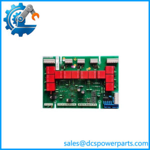
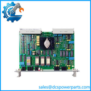
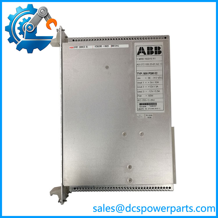
500PSM02 1MRB150015R1 is the module every other card in the rack depends on, and its specification is the one the trade has managed to get wrong in two opposite directions at once. ABB’s manual for the REC 580*3.0 terminal, 1MRK 511 059-BEN, describes the auxiliary supply unit as a DC/DC converter accepting any input voltage from 36 V to 312 V DC without switching of ranges, delivering a maximum of 60 W. That input window is the design intent written plainly: it spans the auxiliary DC battery voltages used in substations — 48 V, 110 V, 220 V and 250 V systems — so that one module serves any of them. One resale page states the input as 24 V DC in a 19.5 to 30 V range; another states 100 to 240 V AC. Both are wrong, and they are wrong in opposite directions, one shrinking the window to a low-voltage control supply and the other turning a DC/DC converter into a mains-input power supply. A card bought on either description will not run in a substation rack.
The supply module’s most consequential property is not electrical but architectural. Redundancy in this rack is not a feature of the card; it is a feature of the backplane and the slot. The manual states that a second supply unit can be inserted to the right of the rack where the 500CRB01 backplane is fitted, either to achieve redundancy or to supply a higher load, and the configuration tables show it: one supply position in a 500CRB02 rack, two in a 500CRB01 rack, the second being the redundancy position. So two 500PSM02 modules in a 500CRB02 rack deliver nothing that one does not — the slot is not there. A plant that believes it has redundant supplies because it holds two modules, on a backplane that carries one, has no redundancy at all, and no test will reveal the difference until the day the supply fails.
Load budgeting is the second architectural point, and the manual points at it with a single line of caution about individual module burdens. A 21-slot rack’s total draw has to fit inside 60 W, and the published consumptions are modest but cumulative: the processor module 7 W, the bus controller 3 W, the star coupler 3.5 W, the analog input unit 6 W, with binary input and output modules on top. Beyond 60 W of dissipation the manual requires forced cooling, which is what the 500LFE01 fan module exists for — four fans, 44 mm high, mounted directly under the terminal, 90 to 250 V DC. This is the reason a 500PSM03 at 100 W is not simply a bigger version of the same answer: it comes with a thermal obligation, and the casing losses differ accordingly, 20 W for the 60 W unit against 10 W for the 100 W one.
The identity layer that the market carries without explaining is the assembly designation. Nearly every listing for this module prints AD-272.100.20-01 AZ:C beside the order code, and that string is not an order number at all: it is an assembly or board designation in ABB’s older drawing-number style, with AZ:C appended as a change status — the letter recording how many times the assembly print has been revised, here at C. Read that way, it is useful rather than noise: it tells a buyer which print revision the unit was built to, independently of the 1MRB ordering code and its R1 release. Both layers being present on a label means the two can be cross-checked against each other, and a mismatch between them is worth a question before the card goes into a bay.
Everything else the trade attaches to this number is either trivially right or plainly invented. Power supply module is correct. A “wide range dynamic power module” is half-right, since the 36 to 312 V window is genuinely wide, with “dynamic” added for effect. And one page declares the model to be KVC758 or KVC758A124 and then describes the card as an analog input module — a different product, a different model number, and a description that contradicts its own title.
Technical Specifications
| Parameter | Value |
|---|---|
| Module designation | 500PSM02 |
| Order code | 1MRB150015R1 — base 1MRB150015, release R1 (R0001 in long form) |
| Assembly designation | AD-272.100.20-01 AZ:C — assembly or board number with change status C |
| Module type | Auxiliary supply unit, DC/DC converter |
| Platform | REC 580*3.0 bay control terminal, manual 1MRK 511 059-BEN |
| Input voltage | 36 to 312 V DC, permissible without any switching of ranges |
| Input power | ≤80 W at full load and 48 V input |
| Output power | Maximum 60 W |
| Casing internal loss | Maximum 20 W |
| Voltage interruption bridging time | >50 ms |
| Redundancy | Second unit to the right of the rack, 500CRB01 backplane only; one supply position in 500CRB02 |
| Cooling requirement | Dissipation above 60 W requires forced cooling; 500LFE01 fan module, 4 fans, 44 mm high, 90–250 V DC |
| Backplane / rack | 500CRB01 or 500CRB02, 21 slots; rack 483 × 266 (6U) × 320 mm |
| Larger sibling | 500PSM03 — 100 W output, ≤140 W input at 48 V, casing loss max 10 W, order code seen as 1MRB150038R0001 |
500PSM02 1MRB150015R1
Key Features and Advantages
One input window for every station battery: 36 to 312 V DC without range switching covers 48 V, 110 V, 220 V and 250 V auxiliary systems with a single module — the reason no voltage selector exists on the card.
A DC/DC converter, not a mains supply: the design assumes a station battery behind it. Mains-input and 24 V control-supply descriptions in circulation are wrong in opposite directions and will not run a substation rack.
Redundancy that belongs to the backplane: a second supply position exists only in the 500CRB01 rack. Two modules in a 500CRB02 rack add capacity to a store, not redundancy to a bay.
A load budget instead of a headline: 60 W shared across 21 slots, against published consumptions of 7 W for the processor, 3 W for the bus controller, 3.5 W for the star coupler and 6 W for the analog input unit, with I/O modules on top.
A thermal obligation attached to the bigger unit: above 60 W of dissipation the manual requires forced cooling, which the 500LFE01 fan module provides at 44 mm height. The 100 W module is not simply a larger 60 W module.
Two layers to cross-check on one label: 1MRB150015R1 as the ordering code and AD-272.100.20-01 AZ:C as the assembly designation with change status — one administrative, one engineering, and comparable.
A bridging time worth knowing: >50 ms of voltage interruption ride-through, which is the number that decides whether a brief battery dip resets the terminal or not.
Applications
Substation auxiliary supply for bay control terminals: the module’s purpose in life is to run a REC 580 rack from the station’s DC battery, converting one battery voltage into the rack’s internal rail.
Battery voltage diversity across a substation: 48 V in older installations, 110 V and 220 V in others, 250 V in some — one module type across all of them simplifies spares for a site that has been extended bay by bay over decades.
Redundant supply in critical bays: where a bay’s control must survive a single supply failure, the 500CRB01 backplane with two units is the arrangement, and it is a rack-level decision made at installation rather than a module-level option.
Load expansion within a rack: additional I/O modules consume additional watts, and the 60 W ceiling is what eventually decides whether a rack needs the larger 500PSM03 or the 500LFE01 fan module.
Replacement of a failed supply in an installed terminal: the commonest real demand for this card, and the one where the input-voltage misconception causes the most wasted purchases.
Where it does not fit: mains-input applications, 24 V control-supply systems, analog input duty, or any role outside the supply position of a 500CRB01 or 500CRB02 rack. Those descriptions exist in the trade; none of them matches ABB’s own module list.
Related Products
500PSM03 (1MRB150038R0001) — the 100 W sibling, ≤140 W input at 48 V and casing loss max 10 W; the same function at higher capacity and with a cooling obligation. 500LFE01 — the forced cooling fan module, four fans at 44 mm height, 90–250 V DC; required wherever dissipation exceeds 60 W. 500CRB01 / 500CRB02 — the two 21-slot backplanes; the only ones that decide whether a second supply position exists. 500CPU03 — the terminal’s processor module, 7 W, with two Industry Pack sockets for bus interfaces. 500MBA02 — the MVB process bus controller module, 3 W. 500SCM01 — the star coupler module, 3.5 W, five optical transmitter/receiver pairs. 500AIM02 — the analog input unit, 6 W, sixteen channels at 1.0/1.2 kHz. 500MTM02 (1MRK001967-AA) — the input transformer module, the mandatory partner of the analog input unit. 500ITM02 — the isolating transducer module, 3/8/16 channels of ±5 mA, ±20 mA and ±10 V.
Installation and Maintenance
Before installation: confirm the rack’s backplane and the intended supply arrangement before the card is unpacked. A 500CRB01 rack has a second supply position to the right and can be made redundant; a 500CRB02 rack has one. Then check the total load against 60 W using the published module consumptions plus whatever the binary I/O cards draw, and establish whether the rack’s dissipation already requires the 500LFE01 fan module. Finally cross-check the two identity layers — 1MRB150015R1 and the assembly designation with its change-status letter — against the bay’s record.
Installation: this is a live-battery job in most plants. Isolate the incoming auxiliary supply, prove it dead at the terminals, and only then work on the supply position; station batteries are capable of very high fault currents and hold their voltage without any indication of danger. Land the input with correct polarity — reverse connection on a DC/DC converter of this class is not a protected condition — and verify the input voltage actually present against the 36 to 312 V DC window rather than assuming it. After energising, confirm output presence, measure the rack’s rail under load, and verify the >50 ms bridging behaviour only where the plant’s test procedure requires it.
Maintenance: the useful checks are thermal and electrical rather than functional. Inspect the module’s casing and connector for discolouration, since casing loss of 20 W is dissipated inside the rack, and confirm fan operation where 500LFE01 is fitted — a fan failure raises an alarm on low speed, but the alarm is only useful if it is wired and monitored. Record which backplane the plant has and whether a second supply position is populated, because that record is the difference between believing in redundancy and having it.
Warranty and Quality
Every 500PSM02 1MRB150015R1 module is supplied as the auxiliary supply unit of ABB’s REC 580 bay control terminal, documented by designation, order code, release R1, and the assembly designation with its change-status letter, so that administrative and engineering layers can be cross-checked. Units are inspected for casing discolouration, input and output connector condition, backplane-interface condition, PCB and assembly damage, rework evidence, corrosion and label legibility; verification covers power-up presence and output delivery under load where a compatible rack is available. Electrical data is quoted from ABB’s manual for the terminal, 1MRK 511 059-BEN: input 36 to 312 V DC without range switching, ≤80 W at full load and 48 V input, maximum output 60 W, casing loss maximum 20 W, bridging time above 50 ms, redundancy only via a second unit on a 500CRB01 backplane, and forced cooling required above 60 W dissipation. The circulating input-voltage claims are corrected rather than repeated: 24 V DC in a 19.5–30 V range and 100–240 V AC are both incompatible with the documented 36–312 V DC window. A 12-month repair, replacement or refund commitment applies. Technical support covers what this part actually requires: establishing whether the rack’s backplane provides a redundancy position, budgeting the 21-slot load against 60 W, deciding between this module and the 100 W 500PSM03 with its cooling obligation, and reading the assembly change-status letter against the ordering code on the unit’s own label.