Description
Product Overview
500PSM03 1MRB150038R1 is the designation as ABB issues it, without the trailing letter that the trade habitually adds, and that difference is worth one sentence and no more: the card bought under 500PSM03A and the card bought under 500PSM03 are one module, and ABB’s own COM581 ordering table settles which form is canonical by printing 500PSM03 1MRB150038 R0001. Everything else about this order is about where the unit goes and what it can carry, because those are the two things that decide whether an installation works.
The rack’s geometry is more informative than it first appears. In the COM581 gateway, the 21 slots are assigned by function rather than by availability: supply units occupy slots 1–2 and 20–21, communication processor boards the odd slots 3, 5, 7 through 19, and star couplers the even slots 4, 6, 8 through 18. Nine processor boards and eight couplers are the maximum. What that mapping says is that power enters the rack at both extremities — the supply positions are at the two ends, not in the middle — and that the boards between them alternate by role. For anyone repopulating a gateway, this is the practical map: a spare supply belongs at an end, a communication board in an odd slot, a coupler in an even one. ABB’s own manual warns that inserting a unit in the wrong slot can damage components, and the slot map is the reason the warning exists.
The rail arithmetic is the second thing worth doing before the card is fitted, and it is arithmetic nobody in the trade performs. The four outputs are rated at 8 A on 3.3 V, 16 A on 5 V, 3 A on 12 V and 0.5 A on −12 V — which, multiplied out, would be roughly 26 W plus 80 W plus 36 W plus 6 W, or about 148 W if every rail were loaded to its individual maximum at once. The unit’s total output is 100 W. So the per-rail figures are ceilings on each rail, not a budget, and the binding constraint is the total. A rack designed by adding up ampere figures per board and checking each rail separately can be comfortably inside every individual limit and still be drawing more than the supply can deliver. The correct procedure is to sum each board’s consumption, allocate it across the rails the board actually uses, and keep the total under 100 W with margin for inrush and for the tolerance monitoring to stay in range.
Two host products share this card, and each arranges redundancy in its own way. In a COM581 rack, two units in the paired supply positions operate as redundant parallel supplies through a load-balancing circuit, with a yellow LED and the unit’s warning relay reporting when one of the pair has failed. In a REC 580 bay terminal, the second supply occupies the additional position that only the 500CRB01 backplane provides, so redundancy there is a property of the backplane order code rather than of the rack’s population. Neither arrangement is better than the other; they are answers to different rack designs, and a plant that assumes one while holding the other has redundancy on paper only.
The input side is identical in both hosts and is the reason this card is a substation part rather than a general-purpose supply: 36 to 312 V DC, which ABB states equivalently as 48 V −25 % to 250 V +25 %, accepted without any range switching. Behind it sits a 10 A / 250 V slow fuse and an inrush limit of 10 A, with an external miniature circuit-breaker of type S282 UC-K 6 recommended upstream. Those figures are the whole of the upstream protection design, and they are the part of this module’s documentation that no listing reproduces.
What the market says about the card is, at this point in the family’s history, almost a genre of its own: an AC500 PLC supply, a component of INFI 90 and Symphony Plus racks, a main control board supporting communication protocols. Each is contradicted by ABB documentation that places the unit in a bay terminal and a station gateway, and by the simple fact that a card cannot be a main control board while also being the thing that feeds one.
Technical Specifications
| Parameter | Value |
|---|---|
| Module designation | 500PSM03 — ABB ordering form; trade also prints 500PSM03A |
| Order code | 1MRB150038R1; official list 1MRB150038 R0001 |
| Module type | Power supply unit, DC/DC converter, electrically insulated input to output |
| Output power | 100 W total — the binding limit |
| Output rails | +3.3 V DC 8 A, +5 V DC 16 A, +12 V DC 3 A, −12 V DC 0.5 A, each an individual maximum |
| Rail arithmetic | Individual maxima summed ≈148 W, well above the 100 W total; per-rail ratings are ceilings, not a budget |
| Output monitoring | Tolerances continuously monitored; green LED extinguishes on short-circuit or overload of any rail |
| Input voltage | 36–312 V DC = 48 V −25 % to 250 V +25 %; no range switching |
| Input protection | 10 A / 250 V slow fuse; inrush limited to 10 A; external m.c.b. type S282 UC-K 6 recommended |
| Input power | ≤140 W at full load, 48 V input; casing internal loss max 10 W; bridging time >50 ms |
| Slot positions — COM581 | Supply 1–2 and 20–21; processors 3, 5 … 19; star couplers 4, 6 … 18; 21 slots; max nine processor boards and eight couplers |
| Slot positions — REC 580 | One supply position in a 500CRB02 rack; two in a 500CRB01 rack, the second for redundancy |
| Redundancy mechanism | COM581: two units in parallel with a load-balancing circuit, yellow LED plus warning relay. REC 580: second unit in the backplane’s extra position |
| Front panel | On/off switch that does not isolate the input; green supply connector must be withdrawn for removal |
| Sibling | 500PSM02 — 60 W, 1MRB150015R1, same input window, one position in 500CRB02 |
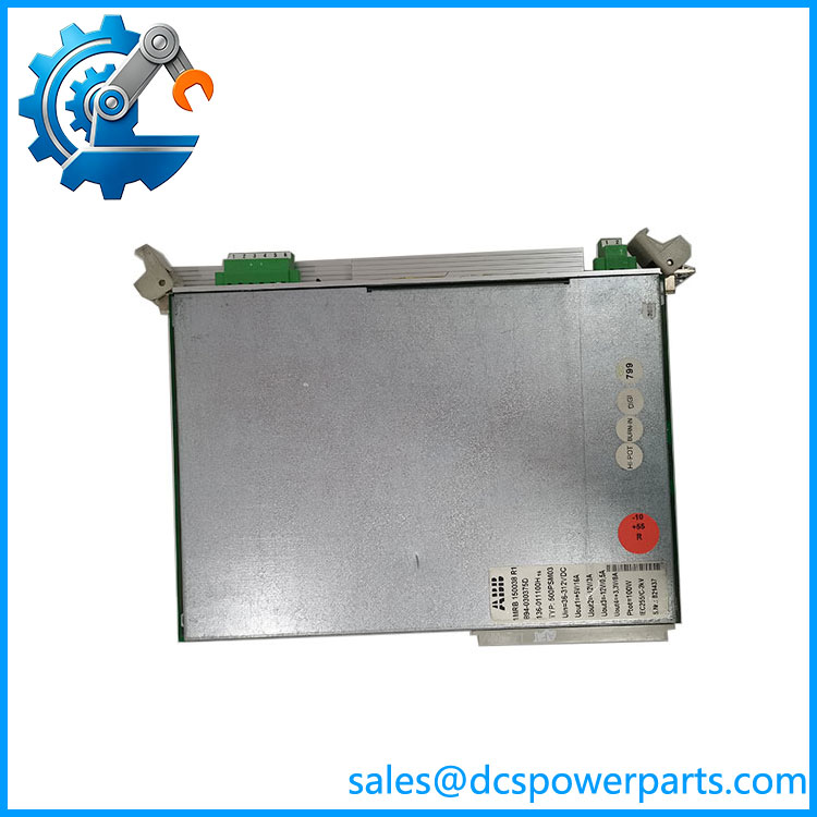
500PSM03 1MRB150038R1
Key Features and Advantages
A canonical designation: ABB’s ordering list has no trailing letter, and the trade’s 500PSM03A is the same card. The order code, not the letter, is what a purchase should be keyed to.
Power at both ends of the rack: supply positions at slots 1–2 and 20–21 in a COM581, with processors in odd slots and couplers in even ones. A card fitted to the wrong position can damage the backplane, which is why the map matters more than the watts.
An arithmetic the ratings invite you to get wrong: 8 A, 16 A, 3 A and 0.5 A on four rails multiply out to about 148 W against a 100 W total. Per-rail figures are ceilings; the total governs.
Four rails, continuously watched: 3.3 V, 5 V, 12 V and −12 V, all inside tolerance-monitored limits, with the green LED going dark on any short-circuit or overload — a single-rail fault that announces itself instead of hiding.
Two redundancy mechanisms for one card: load-sharing between paired units in a gateway, an extra backplane position in a terminal. The mechanism is an installation decision, not a module option.
Protection figures that finish the design: 10 A / 250 V slow fuse, 10 A inrush limit, external MCB type S282 UC-K 6. Nothing else in this module’s documentation constrains the upstream panel so precisely.
A switch that leaves the input live: the front on/off control puts the unit on standby, not on isolation. Removal requires the source switched off and the green connector withdrawn.
Applications
Redundant supply for substation gateways: a carrying up to nine communication boards and eight star couplers across the protocols a utility needs — IEC 60870-5-101/103/104, DNP 3.0, IEC 61850, RP570/571, TG809 — fed by a pair of units at the two ends of the rack.
Bay control terminals in medium-voltage substations: the supply behind a REC 580 rack, where the redundancy option depends on whether the backplane is 500CRB01 or 500CRB02.
Mixed battery voltages on one site: 48 V, 110 V, 220 V and 250 V auxiliary systems all inside one input window, so a single spare part number covers a fleet built over several decades.
Capacity planning before purchase: the 100 W ceiling, evaluated against the sum of board consumptions rather than per-rail ampere figures, is what decides between this unit and the 60 W 500PSM02.
Replacement of one unit of a redundant pair: the yellow LED and warning relay identify which unit failed, and the replacement has to match the surviving partner’s build as well as its rating.
Where it does not fit: AC mains supplies, 24 V control systems, AC500 racks, INFI 90 or Symphony Plus racks, main-control-board or communication duty. ABB documentation places it in a bay terminal and a gateway, as the supply.
Related Products
500PSM02 (1MRB150015R1) — the 60 W sibling, same 36–312 V DC window, one position in a 500CRB02 rack. 500LFE01 — forced cooling fan module, four fans, 44 mm height, 90–250 V DC; required above 60 W dissipation in a terminal rack. 500SCM02 (1MRB150037R0001) — star coupler board of the ordering table, fitted in even slots; distinct from the terminal’s 500SCM01. 500CIM06 (1KHL150005R000x) — the gateway’s communication processor board, ordered as configured variants per protocol; up to nine in a . 500LBI02 (1MRB178032R0010) — LON ancillary board from the same ordering table. 500CPU03 — processor module of the REC 580 terminal, controller of the internal VME bus with two Industry Pack sockets. 500MBA02 — MVB process bus controller module of the terminal. 500AIM02 / 500MTM02 (1MRK001967-AA) — analog input unit and its mandatory input transformer companion, both supplied from this unit. 500CRB01 / 500CRB02 — the terminal’s 21-slot backplanes; only one of them provides the redundancy position.
Installation and Maintenance
Before installation: confirm the host and the slot before anything else. In a the supply belongs in slot 1 or 2 or slot 20 or 21 — nowhere else — and processors and couplers occupy their own alternating positions; in a REC 580 terminal the supply position is set by which backplane the rack carries. Then check the total load against 100 W by summing board consumptions, not by reading ampere figures per rail, and confirm the upstream protection matches the 10 A / 250 V slow fuse and the S282 UC-K 6 recommendation.
Installation: the front-panel switch does not isolate the input, so the sequence is external isolation first, green connector withdrawn, input proven dead with a tester, and only then the card. Seat it fully, restore the connector, and energise. Verify all four rails under load rather than checking presence: a card that reports green can still deliver a rail that has drifted to its tolerance limit, and the tolerance monitoring is a warning, not a guarantee. Where a redundant partner exists, confirm load sharing is actually operating by observing the pair under load, and confirm the warning relay is wired to something that will be read.
Maintenance: treat the two LEDs as the routine diagnostic — green for rail health, yellow for partner health — and keep the warning relay in service if redundancy is claimed. Check the fuse is the correct 10 A / 250 V slow type after any intervention, since a substituted fuse changes the coordination the documentation assumes. Record the host, the slot and the unit’s label strings before removal; those strings are how a replacement is matched years later, and a supply card sourced on designation alone may fit perfectly and carry the wrong build.
Warranty and Quality
Every 500PSM03 1MRB150038R1 unit is supplied as the 100 W power supply of ABB’s 500xxx rack family, documented by designation, order code, and the ABB ordering form 500PSM03 1MRB150038 R0001, with the trade’s trailing letter noted as a naming habit rather than a different product. Units are inspected for casing and connector discolouration, fuse type and rating, front-panel switch and LED condition, backplane-interface condition, PCB damage, rework evidence and label legibility; verification covers power-up presence and output of all four rails under load where a compatible rack is available. Electrical data is quoted from ABB documentation: the operating instructions 1MRB520267-Uen Rev. D and the REC 580 terminal manual 1MRK 511 059-BEN — 36–312 V DC input (48 V −25 % to 250 V +25 %), 100 W total output, rails at +3.3 V/8 A, +5 V/16 A, +12 V/3 A and −12 V/0.5 A with continuous tolerance monitoring, 10 A/250 V slow fuse, 10 A inrush limit, casing loss max 10 W, bridging above 50 ms, and the slot maps for both hosts. The AC500, INFI 90/Symphony Plus and main-control-board attributions are rejected against those documents. A 12-month repair, replacement or refund commitment applies. Technical support covers what this part actually requires: budgeting the 100 W total rather than four separate rail maxima, confirming the host’s redundancy mechanism and backplane, keeping the unit out of processor and coupler slots, specifying the upstream fuse and breaker, and observing that the front switch leaves the input live.