Description
Product Overview
500TRM02 1MRB150011R0001 occupies a position that is easy to describe and hard to define, and the honest starting point is the second of those. ABB’s manual for the REC 580*3.0 bay control terminal describes its rack modules one by one: the supply units 500PSM02 and 500PSM03, the processor 500CPU03, the bus controller 500MBA02, the star coupler 500SCM01, the input transformer module 500MTM02, the isolating transducer 500ITM02, the analog input unit 500AIM02, the binary input 500BIM01, the binary output 500BOM01, and the cooling module 500LFE01. 500TRM02 is not among them. It appears in no slot table, no technical data table, no terminal designation figure and no ordering list in that document. What follows from that is not that the card does not exist — it is traded, and the order code is real — but that its function has to be established from the hardware rather than from the family’s own documentation.
The strongest single piece of evidence concerns the reading of the letters, and it cuts against the obvious one. A card called TRM invites the expansion “terminal”, and in most racks that would be a fair guess: a terminal module is the thing field wiring lands on. In this rack it is not, because the manual is explicit about where terminals are. They are located at the rear of the binary I/O units and the input transformer modules, and the terminal data belongs to those cards: 2.5 mm² for binary inputs, 2.5 mm² for binary outputs, 4.0 mm² for analog inputs, with terminals rated IP20 inside a housing rated IP30. In other words the terminal layer of this terminal is part of 500BIM01, 500BOM01 and 500MTM02, not a separate board. A standalone “terminal module” would have nothing to terminate that those three cards do not already handle, so the expansion is plausible as a name and unsupported as a function.
The market readings of this card are, meanwhile, five different products. One page calls it a transformer monitoring relay and places it in a “500 series relay product system” — a category that does not exist in this family, and a relay function that no bay terminal rack provides. Another calls it a transformer module or terminal/input-output board inside a busbar protection family, where the transformer function is already owned by 500MTM02, documented as the input transformer module with up to thirteen transformers, protection and metering current transformers and potential transformers, ordered channel by channel. A third calls it a coupler module, where the optical coupler is 500SCM01 and the bus controller is 500MBA02, both with published functions. A fourth reduces it to “control card”, which says nothing. A fifth files the same part number under a Bailey INFI 90 category and gives it a “communication speed” and “isolation between channels” — numbers with no source behind them, on a platform that does not use this numbering. Each reading collides with a module that already owns the function, and that collision is the reason none of them should be adopted.
What can be established is structural, and it is worth stating precisely. The block numbers of this family run in clusters that match function: 150003 carries the bus adapters, 150004 the star coupler, 150005 the combined binary I/O, then 150011, then 150015 for a supply unit, 150020 to 150024 for the transformer, transducer and analog I/O cluster, 150037 for the gateway’s star coupler, 150038 for the 100 W supply, 150051 for the communication and control processors, 150077 for the gateway’s communication board. The gaps in that sequence — 150006 to 150010, 150012 to 150014 — are where sibling cards we have no documentation for would sit, and 150011 falls inside exactly such a gap. That places this card in a sub-cluster the available material never covers: not the supply cluster, not the I/O cluster, not the processor pair.
The ordering structure is consistent and does not need inventing. 1MRB150011R0001 is the module code; R0001 and the short form R1 are one release, since this family writes releases in both lengths interchangeably and no document distinguishes them. No assembly code of the 1MRB2000xx type is published for this block, which is itself informative: the assembly layer is documented for the cards whose internals ABB describes, and its absence here matches the absence of the card from the same document.
Technical Specifications
| Parameter | Value |
|---|---|
| Module designation | 500TRM02 |
| Order code | 1MRB150011R0001; equivalent short form 1MRB150011R1 |
| Manufacturer | ABB, Sweden |
| Module type | Rack plug-in module, 500-series — function not published by the OEM |
| Platform | REC 580*3.0 bay control terminal; manual 1MRK 511 059-BEN |
| Block number | 1MRB150011, isolated between 150005 (500BIO01) and 150015 (500PSM02) |
| Assembly code | None published for this block |
| OEM documentation status | Not listed among the ten module descriptions, slot tables, technical data tables or ordering lists of the terminal manual |
| Rack context | 21 slots, 483 × 266 (6U) × 320 mm, backplanes 500CRB01 or 500CRB02 |
| Terminal data of the rack (not of this card) | Binary in/out 2.5 mm², analog in 4.0 mm²; terminals IP20, housing IP30 |
| Rack communication levels | Station LON, service optical RS-232, process optical MVB |
| Rack supply rails | +3.3 V, +5 V, +12 V, −12 V from 500PSM02 / 500PSM03 |
| Verification requirement | Label, slot width and connector type on the physical unit — the only authority for function |
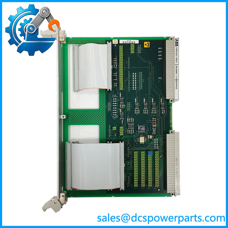
500TRM02 1MRB150011R0001
Key Features and Advantages
A real order code with an undocumented function: the block 1MRB150011 is traded and the release is consistent, but no OEM text assigns it a role. Buy the code, verify the label, do not buy the description.
An evidence-based negative: terminals in this rack live on 500BIM01, 500BOM01 and 500MTM02 at 2.5 mm² and 4.0 mm², terminals IP20 inside an IP30 housing. A separate “terminal module” has no function left to perform.
Collisions that eliminate the trade readings: the transformer function is 500MTM02, the optical coupler 500SCM01, the bus controller 500MBA02. Descriptions that duplicate an existing card’s job are not descriptions of this one.
Block-map reasoning as a tool: 150011 sits in a documented gap between 150005 and 150015, so its siblings are cards the material does not cover — useful when a second unidentified number from the same gap appears.
Slot mechanics that apply whatever the card turns out to be: boards marked as using two slots always take the slots to the right, unused slots receive cover plates, and preferred and alternative positions are distinguished in the terminal’s tables.
Release equivalence without ambiguity: R0001 and R1 denote one release in this family, so a unit labelled either way is not a different build.
An absent assembly code that reads as a signal: the 1MRB2000xx layer is published for the cards ABB describes, and it is absent here — consistent with the card’s absence from the same manual.
Applications
Where a card of this block position is plausibly used: the wiring and interface layer of a REC 580 bay terminal, in racks where the binary and transformer modules carry the field terminations and an additional board handles the transition between them and the rack’s internal wiring.
Retrofit and spare-part supply for installed terminals: the practical case in which this number is encountered — an existing rack needs the board that is fitted, and the label on the removed unit is the specification.
Replacement where documentation is unavailable: matching by order code, block, slot width and connector layout, with a photograph of the installed card as the only reliable comparison.
Where it cannot be used, whatever a listing says: as a transformer monitoring relay, as a busbar protection transformer module, as a star coupler, as a bus controller, or as a Bailey INFI 90 component. Each of those functions is owned by another documented card or belongs to another product family entirely.
Where caution is owed: any application in which the function must be known before the part is ordered. For this number, that means establishing function first and ordering second, not the reverse.
Related Products
500BIO01 (1MRB150005R0001) — combined binary I/O at block 150005, immediately before this block; the nearest documented neighbour. 500PSM02 (1MRB150015R1) — supply unit at block 150015, the next documented block after this one. 500TRM02 short release form 1MRB150011R1 — the same module; listings use both lengths. 500BIM01 (1MRB150024R0002) — binary input module, 24 opto-coupler inputs, one of the cards that carries the rack’s field terminals. 500BOM01 (1MRB150023R0002) — binary output module, 22 contact outputs with six under trip-coil supervision; the other terminal-bearing I/O card. 500MTM02 (1MRK001967-AA) — input transformer module, up to thirteen transformers ordered channel by channel; the card that owns the transformer function. 500SCM01 (1MRB150004R0001) — star coupler, the rack’s optical coupler; not to be confused with any “coupler module” description of this card. 500MBA02 (1MRB150003R0003) — bus controller for the MVB process bus. 500CRB01 / 500CRB02 — the 21-slot backplanes that determine where any of these cards may sit.
Installation and Maintenance
Before installation: identity comes first for this number, because the documentation does not supply the function. Read the label on the unit and on the card being replaced, compare block, release length, slot width and connector layout, and photograph both. Confirm the position in the rack by the rule that a two-slot board takes the slots to its right and that unused slots carry cover plates, then check the rack’s backplane is 500CRB01 or 500CRB02 before assuming any particular slot is available.
Installation: isolate the rack at its source and confirm the supply units are switched off, since boards in this family are not hot-swappable and the supply’s own front switch does not isolate its input. Seat the card squarely, confirm it is not straddling a slot boundary, and check that field terminations — if this card carries any — are made to the documented wire sizes: 2.5 mm² for binary circuits, 4.0 mm² for analog, with terminals at IP20 inside an IP30 housing and therefore no protection against dust ingress at the terminal face.
Maintenance: keep the label photograph with the rack’s records, because it is the only specification this card has; a replacement sourced on designation alone may match the code and differ in function. On removal, note the slot and the neighbouring cards — the block map around 150011 is the best available clue to what a second unidentified board from the same gap might be. Inspect for connector wear, corrosion at the terminal face and evidence of rework, and do not disturb the cover plates of unoccupied slots, which exist to keep the rack’s airflow and dust rating intact.
Warranty and Quality
Every 500TRM02 1MRB150011R0001 unit is supplied with its identity stated as documented and its function stated as unconfirmed — the order code, the block 1MRB150011, the release equivalence between R0001 and R1, and the fact that ABB’s REC 580 manual (1MRK 511 059-BEN) assigns this card no role, no slot position, no technical data and no assembly code. Units are inspected for label legibility and correctness, connector and terminal-face condition, slot-edge and backplane-interface condition, PCB damage, rework evidence and corrosion; the label is photographed and supplied with the unit so that the buyer can compare it against the installed card before fitting. Technical data is limited to what the platform documentation establishes: a 21-slot rack, 483 × 266 (6U) × 320 mm, 500CRB01 or 500CRB02 backplanes, rails at +3.3 V, +5 V, +12 V and −12 V, station bus LON, service interface optical RS-232, process bus optical MVB, and terminal data of 2.5 mm² for binary and 4.0 mm² for analog circuits with terminals at IP20 and housing at IP30. The transformer-monitoring-relay, transformer-module, coupler-module, control-card and INFI 90 attributions are all rejected, each because the function it claims is already documented on another card in the same rack. A 12-month repair, replacement or refund commitment applies. Technical support for this part consists principally of establishing what it is: matching label data, checking slot width and connectors, reading the block map, and confirming the function before an order is placed rather than after.