Description
Product Overview
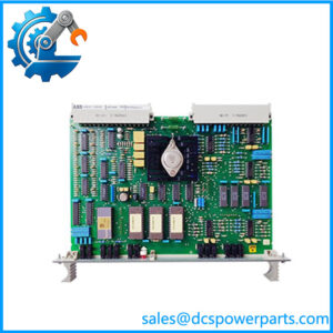
500SCM01 1MRB150004R0001 is the card where the terminal’s process bus stops being copper, and its documentation is unusually concrete about what happens at that boundary. ABB’s manual for the REC 580*3.0 terminal names it the star coupler module and states its function in one line: conversion of electrical bus signals into optical signals, through five optical transmitter/receiver pairs serving the MVB process bus. The letters resolve with it — SCM is a star coupler — and the module’s whole engineering identity sits in the numbers around that function: 62.5/125 µm core and sheath diameter, FST connectors, maximum permissible attenuation of 5 dB, maximum length of approximately 1200 m, two fibre cores per bay unit, and a consumption of 3.5 W.
Those figures are a link budget, and reading them as one is the only way to use the card correctly. A 5 dB allowance over roughly 1200 m of 62.5 µm multimode fibre is not a generous margin: connector losses, splice losses and ageing all consume it, and a bay wired with an extra patch panel or a badly polished FST termination can spend the budget before the distance limit is reached. The 1200 m figure is the distance the fibre can carry the signal; the 5 dB figure is what the receiver needs; and an installation that satisfies one while exceeding the other will work on a cool commissioning day and fail in service. The launch power, the receiver sensitivity and the exact wavelength are not stated in the terminal manual, which is why the attenuation measurement matters more here than on any other card in the rack: it is the only number a technician can verify on site.
The reason a star coupler exists at all is topology rather than taste. An electrical process bus can be shared along a backplane, but not across a substation: at distance, copper carries noise, ground potential differences and surge currents between bays, and the MVB is not designed to tolerate any of them. Converting to light at the rack boundary removes all three at once and makes the run between cabinets a purely optical proposition. The five pairs are the star’s legs — a coupler rather than a repeater, distributing one bus into several point-to-point optical links, each of which can serve a separate bay unit or a distributed I/O station, with different electrical bus signals assignable to the five interfaces.
The module’s presence in a particular rack depends on that rack’s configuration, and the manual is explicit about it. A supplementary star coupler is necessary for connection to the basic rack if there are no analogue input units 500AIM02 in it, and where a second rack is added for capacity, it is joined over the MVB process bus with a 500MBA02 in the basic rack and an 500AIM02 in the extension rack. In other words the coupler is not a universal fitting: it is the element that appears when the bus has to leave the cabinet by fibre, and its slot provision in the terminal’s tables reflects that by allowing it across a wide range of positions rather than one fixed place.
The ordering structure has the same two-layer shape as the rest of this family, now confirmed by a second pair of documents. 1MRB150004R0001 is the module; 1MRB200059/C is the assembly inside it, the same relationship as 1MRB150005R0001 to 1MRB200060/E on the combined binary I/O card. And the block position confirms where the bus electronics sit in the series: 150003 carries the 500MBA01 and 500MBA02 bus adapters and 150004 carries this coupler, so the two cards that own the electrical and optical ends of the same bus occupy adjacent numbers at the head of the block — ahead of the terminal and I/O cards that use the bus.
Transcription, finally, has been unusually cruel to this particular number. The same module appears in circulation as 1MRB150004R0001, as 1MRB15004R0001 with a digit dropped, as 1MRB150044R0001 with one added, and as 1MRE450004R1 with the prefix mangled beyond recognition; release R1 and R0001 also alternate. Meanwhile the descriptions attached to it wander as far as the codes: a signal converter and station control module inside the REB500 busbar protection family, a SIL 3-certified safety communication module from the Relion 615 series, a control module, and a module for an engineering station. None of those is a star coupler, and the SIL 3 claim deserves the same answer it always does: functional safety is a certified property documented per module, and this card’s documentation contains no such claim.
Technical Specifications
| Parameter | Value |
|---|---|
| Module designation | 500SCM01 — star coupler module |
| Order code | 1MRB150004R0001 — block 1MRB150004, release R0001 |
| Assembly code | 1MRB200059/C — the printed circuit board assembly inside the module |
| Module type | Optical star coupler for the MVB process bus |
| Platform | REC 580*3.0 bay control terminal, manual 1MRK 511 059-BEN |
| Function | Conversion of electrical bus signals into optical signals |
| Optical interfaces | 5 optical transmitter/receiver pairs for the MVB process bus; different electrical bus signals assignable to the five interfaces |
| Fibre type | 62.5/125 µm core and sheath diameter |
| Connector type | FST, for 62.5 µm optical fibre cables |
| Permissible attenuation | ≤5 dB maximum |
| Maximum length | Approximately 1200 m |
| Fibre per bay unit | 2 cores |
| Consumption | 3.5 W |
| Configuration rule | Supplementary coupler required for connection to the basic rack if there are no 500AIM02 analog input units; extension racks join over MVB with 500MBA02 in the basic rack and 500AIM02 in the extension |
| Block neighbours | 150003 — 500MBA01 / 500MBA02 bus adapters, the electrical end of the same bus |
| Gateway sibling | 500SCM02 (1MRB150037R0001) — the star coupler board of the COM581 gateway |
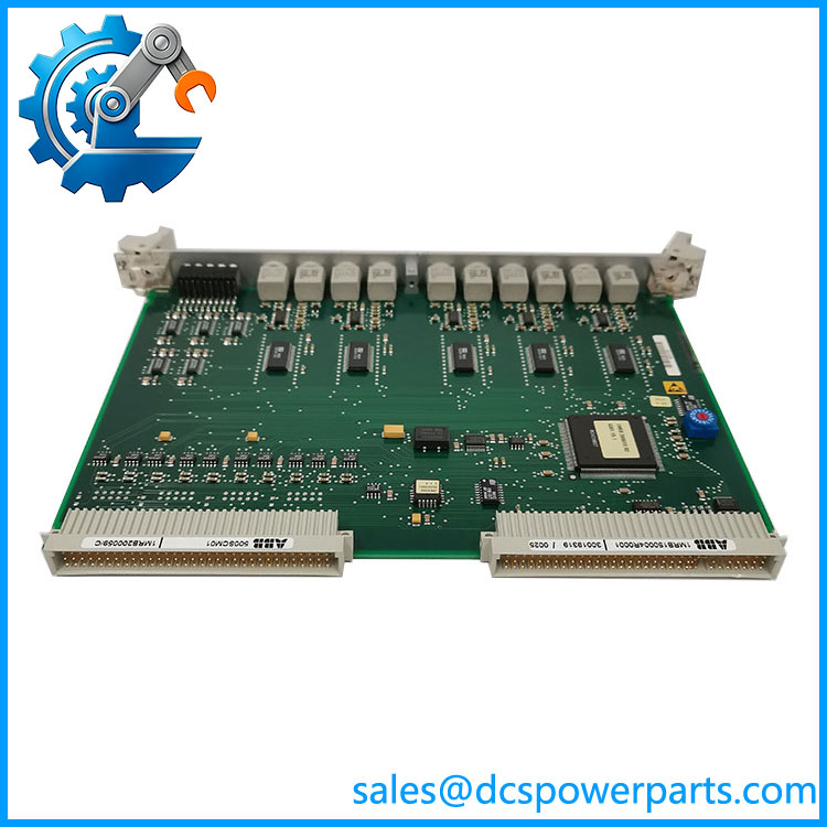
500SCM01 1MRB150004R0001
Key Features and Advantages
A published link budget instead of a distance claim: 5 dB permissible attenuation over approximately 1200 m of 62.5/125 µm multimode, with FST connectors. Both limits bind, and the attenuation is the one a technician can measure.
Five optical legs from one bus: five transmitter/receiver pairs, each assignable a different electrical bus signal — a star coupler distributing the MVB into point-to-point optical links.
Two cores per bay unit: the fibre count is prescribed, so cable ordering and spare capacity follow from the rack plan rather than from guesswork.
Isolation bought by conversion: light removes ground potential differences, conducted noise and surge transfer between cabinets, which is the entire reason a substation bus leaves the rack optically rather than electrically.
A fitted-when-needed module: its presence depends on whether the rack holds 500AIM02 units and whether a second rack is joined over the MVB — a configuration question, not a default.
A two-layer identity verified twice in this family: 1MRB150004R0001 the module, 1MRB200059/C the assembly — the same relationship as 1MRB150005R0001 to 1MRB200060/E.
Neighbours that locate it: 150003 for the bus adapters, 150004 for this coupler — the electrical and optical ends of one bus, adjacent in the block.
Catalogue claims to discard: REB500 signal converter, Relion 615 SIL 3 safety module, control module, engineering-station module. This card converts a bus to light; it certifies nothing.
Applications
Optical process bus in bay control terminals: the point where a REC 580 rack’s MVB leaves the cabinet and becomes a fibre run to other bays or to distributed I/O stations.
Ground potential and surge separation across a switchyard: bays at different earth potentials, separated by cable runs through electrically noisy environments, communicate here without any of that reaching the rack.
Distributed I/O and extension racks: a second rack added for capacity joins the basic rack over the MVB, with the coupler and the bus controller forming the link’s two ends.
Retrofit of an existing station’s bus: where an installed terminal’s copper bus no longer reaches a new bay, conversion to fibre at the rack is the usual answer rather than re-engineering the bus.
Test and commissioning work: attenuation measurement across each leg is the routine check on this module, and it is the reason a plant keeps a light source and power meter alongside its spares.
Where it does not fit: busbar protection signal conversion, a certified safety function, control processing, or engineering-station duty. It also does not substitute for 500MBA02, which drives the electrical bus that this card converts.
Related Products
500MBA02 — the MVB process bus controller module at block 150003, with its own processor; the electrical end of the bus this card converts to light. 500MBA01 (1MRB150003R0002) — the first bus adapter variant of the same base. 1MRB200059/C — this module’s assembly code; the inner layer, not a substitute order code. 500AIM02 — the analog input unit whose presence in the basic rack determines whether a supplementary coupler is needed, and which is required in an extension rack. 500SCM02 (1MRB150037R0001) — the COM581 gateway’s star coupler board; a different card for a different host. 500CPU03 — the terminal’s processor module, controller of the internal VME bus, with two Industry Pack sockets for the bus interfaces. 500PSM02 / 500PSM03 (1MRB150015R1 / 1MRB150038R1) — the terminal’s supply units; the 3.5 W this card draws is part of their budget. 500BIM01 / 500BOM01 — the binary I/O modules whose data travels over the bus this card converts. 500CRB01 / 500CRB02 — the terminal’s 21-slot backplanes, which set where the coupler may sit.
Installation and Maintenance
Before installation: establish whether the rack actually requires the coupler — the rule being that a supplementary star coupler is needed for connection to the basic rack when no 500AIM02 units are fitted — and confirm the optical plan against the five interfaces, since each leg can carry a different electrical bus signal. Verify the fibre type is 62.5/125 µm with FST connectors, count two cores per bay unit, and calculate the attenuation budget for the actual route including every connector and splice before the run is accepted.
Installation: never look into a fibre end or a transmitter port, and treat every optical outlet as live until proven otherwise; the light is invisible and the habit is what protects eyes. Clean both connector faces before mating, keep to the cable’s bend radius, and seat the card fully in its backplane position with the rack de-energised. Then measure attenuation leg by leg with a light source and power meter rather than trusting a link that merely “comes up”: a leg at 4.9 dB will work at commissioning and fail in a cold cabinet a year later. Confirm data exchange with the far end on each populated leg, and label the fibres by interface number so that the plant’s drawings match the rack.
Maintenance: connector cleanliness is the dominant failure mode on this card — dust on an FST face costs decibels silently, and the symptom presents as a bus problem rather than an optical one. Re-measure attenuation periodically and after any intervention on the fibre, inspect for kinked or crushed cable in cable trays, and keep the measurement results with the rack’s records. A spare 500SCM01 should be held with a known-good reference fibre and the plant’s attenuation figures, because the module alone cannot tell a technician whether the link is healthy.
Warranty and Quality
Every 500SCM01 1MRB150004R0001 module is supplied as the star coupler of ABB’s REC 580 bay control terminal, documented by designation, full order code and the assembly code 1MRB200059/C, with the block number confirmed as 150004 — six digits — against the four- and five-digit variants circulating in the trade. Units are inspected for optical connector condition and cleanliness, transmitter and receiver port condition, backplane-interface condition, PCB and assembly damage, rework evidence, corrosion and label legibility; verification covers power-up presence and, where a compatible rack and reference fibre are available, optical output and link establishment. Technical data is quoted from ABB’s manual for the terminal, 1MRK 511 059-BEN: conversion of electrical bus signals to optical, five transmitter/receiver pairs for the MVB process bus, 62.5/125 µm fibre with FST connectors, maximum attenuation 5 dB, maximum length approximately 1200 m, two cores per bay unit, consumption 3.5 W, and the configuration rule tying a supplementary coupler to the absence of 500AIM02 units in the basic rack. The REB500 signal-converter attribution and the Relion 615 SIL 3 safety-module claim are rejected: this module carries no certified safety function and belongs to a bay control terminal, not to a protection relay family. A 12-month repair, replacement or refund commitment applies. Technical support covers what this part actually requires: confirming the rack genuinely needs a coupler, checking the fibre type and connector against the 62.5/125 µm FST specification, budgeting the 5 dB across the real route, distinguishing this module from the gateway’s 500SCM02, and reading 150004 rather than the truncated strings that circulation has produced.
免费
今天 11:04