Description
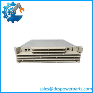
ABB Bailey IEPAS02 | AC System Power Module | INFI 90 DCS Power Replacement
Key Technical Specifications
| Parameter | Specification |
|---|---|
| Product Model | IEPAS02 |
| Manufacturer | ABB Bailey |
| Product Type | AC Input System Power Module |
| System | INFI 90 Modular Power System |
| AC Input | 120 VAC / 240 VAC |
| Input Frequency | 47–63 Hz |
| DC Outputs | +5 VDC, +15 VDC, −15 VDC, +24 VDC |
| Maximum Output Power | 130 W |
| +5 VDC Maximum Current | 13 A |
| ±15 VDC Maximum Current | 0.8 A |
| +24 VDC Maximum Current | 4.0 A |
| Mounting | INFI 90 system power/module mounting unit |
| Function | System DC power conversion |
| Related Earlier Module | IEPAS01 |
The INFI 90 Modular Power System documentation gives the IEPAS02 a 130 W maximum rating, compared with 102 W for the earlier IEPAS01. The documented maximum output currents are 13 A on the 5 V rail, 0.8 A on the ±15 V rails, and 4.0 A on the 24 V rail.
Product Introduction
The ABB Bailey IEPAS02 is an AC-input system power module used in the INFI 90 Modular Power System. Its job is straightforward but system-critical: convert cabinet AC power into the regulated DC buses required by controllers, communication hardware, and other INFI 90 modules. ABB hardware documentation specifically identifies IEPAS02 as an AC input system power module, distinguishing it from IEPAF02, which is an AC input field power module.
The module provides +5 VDC, ±15 VDC, and +24 VDC system power, with a documented maximum capacity of 130 W. IEPAS02 also superseded the earlier IEPAS01, so it is commonly encountered when maintaining older INFI 90 installations.
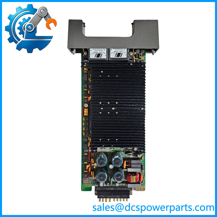
IEPAS02
Application Scenarios & Field Pitfalls — Engineer’s Perspective
Engineering Pain Point
A failed can look like a controller or communication-module failure because several downstream modules may lose power simultaneously. Before replacing individual control cards, check the system power rails and determine whether the failure originates in the AC input, , power mounting unit, distribution bus, or downstream load.
Typical Applications
- INFI 90 DCS Cabinets — primary AC-to-DC system power conversion.
- Legacy Bailey Control Systems — supplies regulated DC rails to system modules.
- Redundant Power Architectures — multiple power modules can share common load buses when correctly matched.
- INFI 90 Maintenance Projects — replacement of earlier IEPAS01 units where the system configuration permits it.
Technical Pitfalls to Avoid
- Do not confuse system power with field power.
is the AC input system power module. IEPAF02 is an AC input field power module. They occupy different roles in the power architecture. - Check load sharing before mixing power modules.
The INFI 90 power documentation states that power modules share the load buses and that equal load sharing depends on their output voltages being equal. Mixing units without checking the applicable power-system configuration is not a safe substitution strategy. - Do not trust generic 220 V listings.
Several current descriptions incorrectly publish a single “220 V” operating voltage or even describe as an I/O module. The documented system architecture identifies it as an AC system power module, with 120/240 VAC input configurations. Verify the actual cabinet wiring and nameplate before energization. - Check the entire power chain.
If an fails repeatedly, inspect the power entry panel, mounting unit, bus connections, downstream load, ventilation, and redundant-module arrangement rather than repeatedly swapping the power module.
Related Products
- IEPAS01 — earlier INFI 90 AC system power module; provides the documented higher-capacity replacement path.
- IEPAF02 — AC input field power module; serves field-power requirements rather than the system power bus.
- IEPDS01 — 24 VDC input system power module for DC-powered system architectures.
- IEPDS02 — 48 VDC input system power module.
- IEPDF01 — 24 VDC input field power module.
- IEPDF02 — 48 VDC input field power module.
- IEPMU01 — power mounting unit associated with the modular power architecture.
- IEPMU02 — alternate power mounting unit configuration.
- IEMMU11 / IEMMU12 — INFI 90 module mounting units with primary power distribution.
- IEMMU21 / IEMMU22 — module mounting units without primary power distribution.
Procurement Note
For an , verify the complete part identification and cabinet power architecture before purchase. The critical checks are 120/240 VAC input configuration, INFI 90 mounting arrangement, required +5 V/±15 V/+24 V loading, redundant power configuration, and condition of the associated power bus.
One important distinction should remain clear: is a system power-conversion module, not a PLC/DCS I/O card. Claims that it provides PROFINET, EtherCAT, analog I/O, digital I/O, or field-device communication are not supported by the INFI 90 documentation and should not be used when specifying a replacement.