Description
Yokogawa YS110-001 Standby Manual Station
Product Overview
The Yokogawa YS110-001 is a standby manual station designed to provide a temporary manual control path when a compatible Yokogawa controller requires replacement or maintenance. Rather than functioning as a standalone PID controller, the YS110 takes over the control output and supplies a 4–20 mA DC signal to the final control element. Yokogawa specifically describes the YS110 as a backup device for YS1360, YS1500, YS1700 and related compatible instruments.
Its field interface consists of one 1–5 VDC input and one 4–20 mA DC operating output. A front-mounted manual operation wheel allows the operator to adjust the output, while upper and lower output limits are provided. The input and output indications use moving-coil meters with a 0–100% scale divided into 20 increments. This is intentionally simple: the YS110 is meant to keep the final element under operator control while the normal controller is unavailable.
For maintenance work, the Yokogawa YS110-001 can be connected through the instrument case using the dedicated connection arrangement. Yokogawa’s documentation describes its use during controller exchange so that the control output can remain backed up while the controller’s internal unit is serviced. The current manual also states that installation in the case is limited to YS1500, YS1700, and YS1360 instruments of the type compatible with YS100.
The unit can operate from three 9 V batteries for approximately one hour, or from external AC/DC power when installed in the appropriate instrument case. Yokogawa specifies 100–120 VAC or 24–120 VDC for the 100 V-class supply arrangement, and 220–240 VAC or 135–190 VDC for the 200 V-class arrangement.
Product Introduction
Controller replacement is normally a poor time to discover that the final control element has no manual backup. The YS110-001 addresses that maintenance problem by providing a dedicated manual 4–20 mA output path while the compatible controller is being exchanged or inspected. Yokogawa explicitly positions the YS110 for this standby role rather than as a general-purpose PID controller.
For a legacy control-system maintenance project, the compatibility check is straightforward but important: verify the controller family, case type, connector arrangement, and YS100-compatible configuration before ordering. The current YS110 manual specifically restricts case installation to compatible YS1500, YS1700, and YS1360 configurations.
Key Technical Specifications
| Parameter | Value |
|---|---|
| Product Model | -001 |
| Manufacturer / Brand | Yokogawa |
| Product Type | Standby Manual Station |
| Series | |
| Primary Function | Manual backup of controller output |
| Input Signal | 1–5 VDC, 1 point |
| Operating Output | 4–20 mA DC, 1 point |
| Input / Output Indication | Moving-coil meter |
| Meter Scale | 0–100%, 20 divisions |
| Output Operation | Upper limit / lower limit |
| Manual Adjustment | Front operation wheel |
| Connection | Dedicated cable / case connector |
| Battery | Three 006P-type 9 V batteries |
| Battery Runtime | Approximately 1 hour |
| External Power | AC/DC |
| 100 V-Class AC Supply | 100–120 VAC, 50/60 Hz |
| 100 V-Class DC Supply | 24–120 VDC |
| 200 V-Class AC Supply | 220–240 VAC, 50/60 Hz |
| 200 V-Class DC Supply | 135–190 VDC |
| Dimensions | 58 W × 144 H × 295 D mm |
| Weight | Approximately 1.6 kg |
| Compatible Controller Families | YS1360, YS1500, YS1700 and specified compatible configurations |
The electrical and mechanical specifications above are taken from Yokogawa’s published specifications.
Major Features / Practical Advantages
Dedicated manual output backup
The primary function is continuity of manual control during controller maintenance. Yokogawa describes the as a device that can output a 4–20 mA signal to the control-valve actuator when the associated controller fails or is being replaced.
That makes it particularly relevant in process applications where shutting down the final element simply to exchange an electronic controller is undesirable.
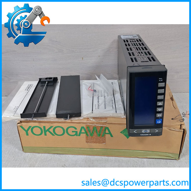
Yokogawa YS110-001
4–20 mA control output
The produces one 4–20 mA DC operating signal. This matches the conventional analog control interface used by many valve positioners and other final control devices.
The unit should not, however, be treated as an independent analog output card. Its purpose is manual standby operation within the Yokogawa instrument ecosystem.
1–5 VDC input
The documented input is one 1–5 VDC signal. This provides the with the associated process/control reference used by the standby arrangement. The input should be checked against the wiring diagram of the specific installation before connection.
Manual output adjustment
A front operation wheel allows the operator to adjust the control output manually. Upper and lower limits are provided, allowing the output range to be constrained during standby operation.
This is an important operational distinction from simply forcing a PLC analog output: the is purpose-built as a physical manual station.
Portable maintenance architecture
The is physically designed to be connected to compatible controller cases. Yokogawa documents a procedure in which the station is inserted into the case and connected through the rear connector.
For maintenance teams, this arrangement reduces the amount of temporary field wiring required during an approved controller replacement procedure.
Battery operation
The unit can operate from three 9 V batteries, with a specified continuous operating time of approximately one hour. This provides a short-duration portable backup capability when external power is not being used.
The one-hour figure should be treated as a specified operating duration, not as a guaranteed field runtime under every battery condition. Battery age and actual operating conditions still matter.
External AC/DC operation
For longer maintenance work, the can operate from the compatible instrument case’s external power arrangement. Yokogawa specifies separate 100 V-class and 200 V-class AC/DC supply ranges.
Controller replacement without immediate loss of output
Yokogawa specifically describes the as part of the controller online-replacement approach. The can back up the control output while the associated controller is exchanged.
This does not mean the independently executes the controller’s PID algorithm. It provides manual output control; process automation logic remains a function of the normal controller.
Compatibility with legacy YS100-related installations
Yokogawa maintains documentation concerning replacement of older YS80 and YS100 equipment with the YS1000 family. The is specifically associated with the standby/maintenance architecture used around these controller families.
The exact case and compatibility code still need to be checked before procurement.
Related Products
- YS1360 — Yokogawa programmable indicating controller/manual-control instrument that can use the standby station in compatible configurations.
- YS1500 — Yokogawa indicating controller in the YS1000 family, with support for controller maintenance and replacement.
- YS1700 — Yokogawa programmable indicating controller; the provides a portable manual backup function during controller exchange.
- YS1310 — YS1000-series controller; part of the broader Yokogawa single-loop control platform, although compatibility must be checked against the exact case configuration.
- YS1350 — YS1000-series controller associated with the maintenance ecosystem; verify exact compatibility before replacement.
- YS100 Series — Legacy Yokogawa controller family for which Yokogawa provides YS1000 replacement documentation.
- YSS1000 — Yokogawa software environment for configuring YS1000-series devices; it is not a substitute for the physical standby station.
FAQ
Can I use the -001 as a normal standalone PID controller?
No. Its intended role is standby manual operation. It provides a manual 4–20 mA output when the associated controller is unavailable; it is not a general-purpose replacement for the controller’s automatic PID execution.
Can I hot-swap the controller while using the ?
The is specifically designed for controller replacement and maintenance with output backup. Yokogawa describes the standby station as part of the online replacement function. However, the actual replacement procedure must follow the applicable Yokogawa manual and plant maintenance procedure.
What is the output signathe ?
The operating output is 4–20 mA DC. The documented input is 1–5 VDC.
What controllers can the support?
Yokogawa identifies the for use with YS1360, YS1500, YS1700 and related compatible controller configurations. The current manual specifically states that case installation is for , , and instruments of the compatible YS100 type.
How is the powered?
It can operate from three 9 V batteries for approximately one hour. When installed in the appropriate instrument case, it can instead use external AC/DC power.
Does the retain the controller’s PID program?
No. The is a manual standby station. It should not be represented as storing or executing the normal controller’s PID program. Its function is to provide a manually adjusted backup output while the controller is being serviced.
Can I install the in any case?
No. Mechanical and electrical compatibility matters. Yokogawa’s current manual specifically states that the can be installed in , , or cases of the compatible type for .
What are the physical dimensions?
Yokogawa specifies approximately 58 × 144 × 295 mm and a mass of approximately 1.6 kg.
Is the same thing YS110 controller?
No. The is classified by Yokogawa as a Standby Manual Station. Calling it a conventional controller can lead to an incorrect procurement or system-integration decision.
Procurement Note
When sourcing a , verify the complete model marking, compatible instrument case, connector arrangement, power configuration, and intended controller family. The critical issue is not simply obtaining a unit labeled ; it is confirming that the standby station matches the installed Yokogawa controller architecture.
For maintenance inventory, also distinguish new surplus, refurbished, and previously installed equipment. Request photographs of the actual nameplate, rear connector, front controls, meter condition, and battery compartment where applicable. A clean front panel does not establish that the internal connector and manual-output circuitry have been tested.
The ‘s role is unusually specific: it is a maintenance and continuity device intended to keep a 4–20 mA final-control output available during controller replacement or failure. That makes it valuable in an existing Yokogawa installation, but it is not a generic substitute for a single-loop controller or PLC analog-output module.