Description
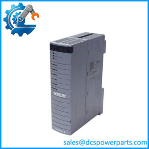
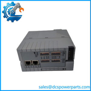
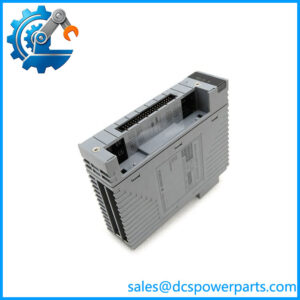
Yokogawa EB501-10 | ER Bus Interface Slave Module
Product Overview
The Yokogawa EB501-10 is an ER Bus Interface Slave Module used in Yokogawa distributed control system architectures to connect a remote node to the ER Bus network. In the Yokogawa architecture, the EB501 operates on the remote-node side while the EB401 serves as the corresponding ER Bus master interface at the control or local node. Yokogawa documentation explicitly identifies EB501 as the ER Bus interface slave module and shows it installed in remote-node configurations alongside I/O modules and power-supply modules.
From an engineering standpoint, the distinction matters. The Yokogawa EB501-10 does not replace an analog input, digital output, or processor module. Its job is to provide the communication path through which the Field Control Unit can access I/O located in a remote node. This arrangement allows I/O hardware to be physically separated from the main control equipment while remaining part of the same DCS architecture. Yokogawa’s documented ER Bus topology uses 10 Mbps transmission over coaxial cable, with YCB141 supporting a maximum segment distance of 185 m. The architecture can use single or redundant transmission paths, depending on the system configuration.
For maintenance and legacy replacement work, EB501-10 should therefore be treated as an architecture-specific communication component rather than a generic industrial Ethernet interface. The module belongs to Yokogawa’s CENTUM-era remote-node design, including systems documented around CENTUM CS3000 and later CENTUM VP configurations. Before ordering a replacement, confirm the remote-node type, complete module suffix, connector arrangement, hardware revision, and whether the installation uses a single or dual-redundant EB501 arrangement. Yokogawa documentation specifically shows two EB501 modules being used for a dual-redundant configuration.
Product Introduction
Remote I/O troubleshooting often points engineers toward the I/O card first. With an EB501-10, that can send the diagnosis in the wrong direction. This module sits in the ER Bus communication path, so a failed interface can affect an entire remote-node I/O group rather than one individual signal.
For DCS system upgrades and legacy replacement projects, the useful specification is the network architecture: 10 Mbps ER Bus communication and up to 185 m on a YCB141 segment.
Key Technical Specifications
| Parameter | Specification |
|---|---|
| Product Model | EB501-10 |
| Manufacturer / Brand | Yokogawa |
| Product Type | ER Bus Interface Slave Module |
| Series | |
| System Application | Yokogawa CENTUM DCS remote-node architecture |
| Network Function | ER Bus slave-side interface |
| Communication Speed | 10 Mbps |
| Network Topology | Bus |
| Transmission Cable | YCB141 / YCB311 coaxial cable, depending on system configuration |
| Maximum YCB141 Segment | 185 m |
| Transmission Redundancy | Single or dual-redundant, depending on system configuration |
| Typical Remote Node | ANR10-series ER Bus Node Unit and compatible Yokogawa node architecture |
| Installation | Remote-node module/rack position |
| Working Voltage | Not independently verified he module; confirm the node power configuration |
| Operating Temperature | ct module rating should be confirmed from the applicable hardware specification; do not infer it from the node-unit rating |
| Protection Rating | Not independently verified |
| Operating Accuracy | Not applicable; this is a communications interface rather than a measurement module |
Yokogawa’s documentation confirms the 10 Mbps ER Bus, coaxial transmission, 185 m maximum for YCB141, and availability of redundant transmission. It also identifies as the slave interface used in the remote-node architecture.

EB501-10
Major Features and Advantages
1. Dedicated Remote ER Bus Interface
he has a very specific job: it provides the slave-side interface between the ER Bus and a remote DCS node. Yokogawa’s own system documentation separates the roles of EB401 B501, with EB401 identified as the ER Bus master interface B501 as the ER Bus slave interface.
That makes the module particularly important during remote-node communication faults. If several I/O channels in one remote node disappear simultaneously, checking the , ER Bus cabling, node power, and corresponding master-side interface is more appropriate than immediately replacing individual I/O cards.
2. 10 Mbps ER Bus Communication
The documented ER Bus transmission rate is 10 Mbps. The network uses a bus topology and can operate with single or dual-redundant transmission. For YCB141 coaxial cable, Yokogawa specifies a maximum transmission distance of 185 m per segment.
These numbers should not be confused with ordinary Ethernet specifications. Although the transmission speed is expressed in Mbps, this is a Yokogawa-specific ER Bus architecture with defined cables, adapters, node interfaces, and system rules.
3. Supports Distributed I/O Architecture
A remote-node arrangement places I/O modules away from the primary control equipmehe provides the communication interface needed for that arrangement, allowing the control system to exchange I/O data through the ER Bus.
This is useful in large process installations where remote I/O locations reduce the amount of point-to-point wiring returning to the central control equipment.
4. Redundant Configuration Capability
Yokogawa documentation shows that an ER Bus Interface Slave Module can be installed as a pair when the node is configured for dual redundancy.
For maintenance teams, this means the installed quantity matters. If the existing cabinet uses two modules, purchasing one replacement may solve only part of the problem. Check the actual rack arrangement before placing a spare-parts order.
5. Suitable for Legacy DCS Maintenance
The family appears in Yokogawa’s CENTUM CS3000-era architecture and remains relevant to maintenance of installed legacy systems. Yokogawa documentation for the Compact Field Control Station explicitly identifies as the ER Bus slave module in the remote node.
For a replacement project, exact identification matters more than the generic description “bus interface.” An -family module may look similar to another Yokogawa interface card while having a completely different system role.
Related Products
- EB401-10 — ER Bus Interface Master Module used on the master/local-node side; it is the architectural counterpart to the remote slave interface.
- — Base family designation for the ER Bus slave interface used in remote-node configurations.
- SB401 — ESB Bus Interface Slave Module; functionally different from the because it belongs to the ESB Bus architecture.
- EC401 — ESB Bus Coupler Module used to connect appropriate Field Control Unit configurations to the ESB bus.
- ANR10D — Yokogawa ER Bus Node Unit commonly associated with remote-node architectures containing modules.
- ANB10D — ESB Bus Node Unit; uses a different bus architecture and should not be treated as a direct mounting equivalent.
- — ER Bus coaxial cable with a documented maximum transmission distance of 185 m per segment.
- YCB311 — Alternative ER Bus coaxial cable used in configurations with the appropriate bus adapters and grounding provisions.
- YCB147 / YCB149 — Bus Adapter Units used when connecting and YCB311 cable types.
Yokogawa’s published architecture diagrams show EB401, , ANR10D nodes, ER Bus connections, and associated cable/repeater arrangements as parts of the same system architecture.
FAQ
What is the Ywa used for?
It is an ER Bus Interface Slave Module used at the remote-node side of a Yokogawa DCS architecture. Its purpose is communication between the ER Bus and the I/O resources installed in the remote node.
Is an analog or digital I/O module?
No. It should not be treated as a conventional AI, AO, DI, or DO cahe is a communications interface module. The actual field signal processing remains with the appropriate I/O modules installed in the node.
Can I ce with EB401-10?
Not as a direct functional substitution. and occupy different positions in the ER Bus architecture: is the master-side interface, while is the slave-side interface.
Can I hot-she ?
Do not assume that it can be hot-swapped. The safe procedure depends on the specific Yokogawa node, redundancy arrangement, system revision, and approved maintenance procedure. If the node is controlling a live process, follow the site’s Yokogawa maintenance procedure before removing the module.
es support firmware v3.1?
A reliable firmware-v3.1 compatibility statement could not be established from the documentation reviewed for this exact model. Firmware compatibility should therefore be checked against the installed CENTUM system revision and the module’s hardware/revision marking rather than assumed fhe model number.
Will the module retain my DCS logic or configuration?
he is an ER Bus interface rather than the primary controller holding the process-control application. Do not treat replacement of the module as equivalent to replacing a CPU. Even so, document the existing node configuration and confirm the system’s redundancy and initialization procedure before replacement.
How should I verify a New us before installation?
Check the complete part-number marking, suffix/revision, connector condition, board condition, and compatibility with the installed remote-node hardware. If the module is suppas S2 or another extended designation, record that exact marking rather than reducinto . A “New Surplus” label describes condition or inventory status; it does not by itself prove manufacturing authenticity or system compatibility. Supplier warranty terms and test records should be confirmed before purchase.
Procurement Note
an replacement, the critical question is not simply whether the card powers up. Verify the remote node model, quantity, redundancy arrangement, ER Bus cable architecture, module suffix/revision, and connector condition. Yokogawa’s system documentation shows that the participates in a larger node architecture, so compatibility has to be checked at the system level rather than by appearance alone.