Description
Product Overview
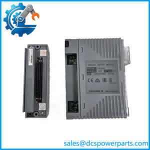
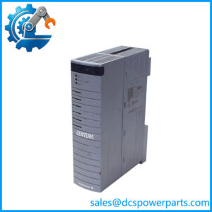
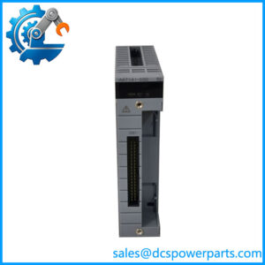
The Yokogawa EB401-10 is an ER Bus Interface Master Module used within Yokogawa distributed control architectures. Its primary job is communication between the control-side equipment and ER Bus segments, making it a communications component rather than a conventional analog or digital I/O card. Technical references identify the physical interface as IEEE 802.3 10BASE-2, with a single BNC connection and a communication rate of 10 Mbps.
In practical DCS work, the Yokogawa EB401-10 belongs to the infrastructure between the control unit and field-side bus nodes. The documented maximum segment distance is 185 meters when using Yokogawa’s specified YCB141 cable. The module is also reported at approximately 0.7 A current consumption and 0.3 kg, with dimensions around 32.8 × 144.65 × 125.5 mm.
Installation details are important. The EB401-10 is designed for particular Yokogawa node/control-unit positions rather than arbitrary rack slots. One technical reference specifies installation in an odd-numbered slot of ESB Bus Node Units such as ANB10S/ANB10D, or compatible Field Control Units including AFF50S/AFF50D and AFV10S/AFV10D, with an adjacent dummy module required in a single-module configuration.
For a legacy DCS replacement, do not confuse the EB401-10 with an ESB bus coupler or a generic Ethernet interface. The module’s 10BASE-2 electrical layer uses coaxial/BNC connectivity, but the application is Yokogawa’s ER Bus architecture. That distinction becomes important when checking cable type, termination, node topology, and the installed control-system hardware.
Product Introduction
A failed bus master can take an otherwise healthy group of remote I/O equipment offline. The EB401-10 provides the ER Bus interface required by compatible Yokogawa control architectures, with a documented 10 Mbps communication rate and 185 m maximum segment length under the specified cable arrangement.
For a DCS legacy replacement, match the complete EB401-10 designation and installed node hardware. The BNC interface, slot position, bus topology, and system generation all need to agree before commissioning.
Key Technical Specifications
| Parameter | Value |
|---|---|
| Product Model | |
| Manufacturer / Brand | Yokogawa |
| Product Type | ER Bus Interface Master Module |
| Primary Function | ER Bus interface |
| Physical Layer | IEEE 802.3 10BASE-2 |
| Communication Speed | 10 Mbps |
| ER Bus Connector | BNC |
| Number of ER Bus Ports | 1 |
| Maximum Segment Distance | 185 m |
| Recommended Cable Reference | YCB141 |
| Current Consumption | Approximately 0.7 A |
| Weight | Approximately 0.3 kg |
| Dimensions | 32.8 × 144.65 × 125.5 mm |
| Compatible Node Hardware | ANB10S / ANB10D and specified Field Control Units |
| Installation | Designated control-unit / node-unit slot |
| Redundancy | Dual-module configuration supported in compatible systems |
| Working Voltage | Not independently verified from the technical references reviewed |
| Operating Temperature | Not independently verified from the strongest references reviewed |
| Protection Rating | Not established for the module itself |
The published technical references also describe suffix options associated with the EB401 family, including standard, explosion-protected, and ISA G3 environmental configurations. Confirm the complete ordering designation before procurement rather than assuming every unit has identical environmental specifications.
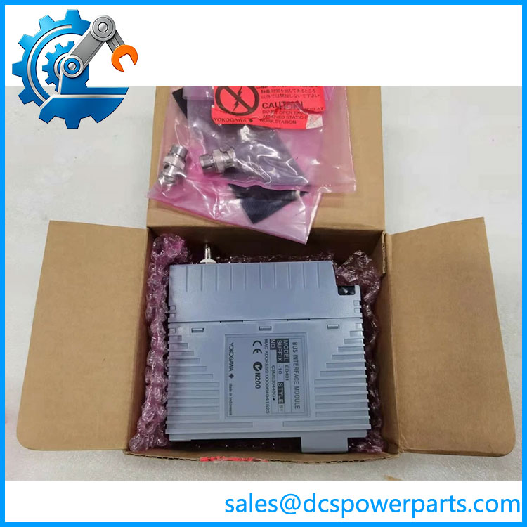
EB401-10
Related Products
- Yokogawa — Base ER Bus interface family from whhe configuration is derived.
- Yokogawa SB401-50 — ESB Bus interface module used in Yokogawa control architectures; it serves a different bus function and should not be treated as act replacement.
- Yokogawa ANB10S — ESB Bus Node Unit that can accommodate -series interface hardware in documented configurations.
- Yokogawa ANB10D — Dual/redundant ESB Bus Node Unit variant used with compatible Yokogawa architectures.
- Yokogawa AFF50S — Field Control Unit configuration identified as compatible with -series installation.
- Yokogawa AFF50D — Redundant Field Control Unit configuration associated with the same architecture.
- Yokogawa AFV10S — Compatible Field Control Unit variant identified in installation documentation.
- Yokogawa AFV10D — Redundant Field Control Unit variant for compatible Yokogawa systems.
FAQ
What is the Ywa ?
It is an ER Bus Interface Master Module used to provide ER Bus communication within compatible Yokogawa DCS/control-system architectures. It is not a standalone Ethernet switch or standard I/O module.
he an Ethernet module?
Technically, its physical layer is identified as IEEE 802.3 10BASE-2, but that does not make it a general-purpose Ethernet interface. It is intended for Yokogawa’s ER Bus architecture, using a BNC/coaxial connection and the specified bus topology.
What communication spees support?
The documented communication speed is 10 Mbps. The maximum specified transmission distance is 185 meters per segment using the referenced YCB141 cable.
Can I hot-she ?
Do not assume that it can be hot-swapped. The module is part of the DCS communication path, and removing it can interrupt connected ER Bus equipment. Follow the Yokogawa-approved maintenance procedure for the installed system.
es support redundant operation?
A redundant arrangement can be implemented using two compatible interface modules in supported Yokogawa control configurations. The exact redundancy architecture depends on the Field Control Unit or ESB Bus Node Unit being used.
es use a standard RJ45 connector?
No. The documented ER Bus physical interface is a single BNC connection using 10BASE-2 coaxial signaling.
es support firmware version 3.1?
A reliable firmware compatibility matrix for a generic “V3.1” designation was not established in the sources reviewed. Firmware compatibility should be checked against the exact Yokogawa system generation, module revision, and installed control-system software.
What should I verify before purchasing a replacement?
Check the cte nameplate, suffix/configuration, installed Field Control Unit or ESB Bus Node Unit, BNC connection, ER Bus cable arrangement, slot position, and redundancy configuration. Also verify whether the existing application requires a standard, explosion-protected, or ISA G3/environmental variant.
Is New us suitable for a legacy Yokogawa DCS?
Potentially, provided the hardware configuration matches the installed system. For a communications module this old, I would document the module revision and nameplate, inspect the BNC interface and backplane connector, power it up in an appropriate test configuration, and verify ER Bus communication before putting it into a live control system.