Description
Key Technical Specifications
| Parameter | Specification |
|---|---|
| Model | ASI133-H00/SA3S0 |
| Manufacturer | Yokogawa |
| Product Type | Analog Input Module with Built-In Barrier |
| Input Channels | 8 |
| Input Signal | 4–20 mA DC |
| Channel Isolation | Isolated analog input channels |
| Communication | HART |
| HART Protocol | HART Revision 5.7 |
| HART Baud Rate | 1200 bps |
| Terminal Assembly | ATSA3S-0 pressure-clamp terminal |
| Environmental Option | ISA Standard G3 |
| Operating Temperature | -20 to 70°C |
| Module Dimensions | 130 × 94 × 32.8 mm |
| Barrier Function | Intrinsic-safety interface for compatible field circuits |
| Installation | Yokogawa FIO node |
Ordering-code clarification: -H00 identifies the HART communication version. /SA3S0 specifies the single pressure-clamp terminal arrangement for analog input. It is not the dual-redundant terminal option /SA3D0.
Product Introduction
Yokogawa ASI133-H00/SA3S0 Analog Input Module
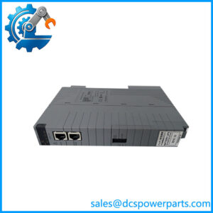
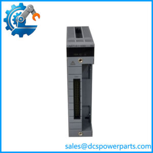
The Yokogawa ASI133-H00/SA3S0 is an eight-channel analog input module with a built-in intrinsic safety barrier, designed for Yokogawa Field I/O (FIO) systems. It accepts 4–20 mA signals from field transmitters and supports HART communication, allowing process measurements and additional instrument variables to reach the control system.
Its integrated barrier reduces the need for separate field-side barrier components in supported installations. The module also supports operation in demanding industrial environments, with a specified ambient temperature range of -20 to 70°C and ISA G3 environmental classification.
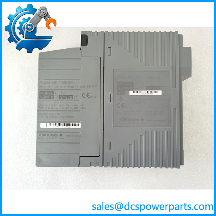
ASI133-H00SA3S0
Application Scenarios & Field Pitfalls (The Engineer’s Perspective)
Engineering Pain Point
A failed analog input channel in a refinery or chemical processing facility can interrupt pressure, flow, or level monitoring. When the affected transmitter is installed in a hazardous area, replacing the interface is more complicated than swapping an ordinary analog input card.
The ASI133-H00/SA3S0 addresses this requirement through an integrated barrier and HART communication capability. It allows compatible field transmitters to deliver their 4–20 mA process signals while providing access to additional HART variables. This is particularly useful when maintaining existing FIO installations without redesigning the entire field interface.
Typical Applications
- Oil and Gas: Acquisition of pressure and flow transmitter signals from hazardous-area field instruments.
- Petrochemical Processing: Monitoring distillation column pressure, tank levels, and process flow through 4–20 mA transmitters.
- Power Generation: Monitoring fuel pressure, cooling-water flow, and auxiliary process measurements.
- Water Treatment: Collecting level, pressure, and flow measurements from remote instrumentation.
- Chemical Manufacturing: Integrating HART-compatible transmitters for process measurement and instrument diagnostics.
Technical Pitfalls to Avoid
1. Do Not Confuse Field Isolation with Channel-to-Channel Isolation
This is an important distinction.
Yokogawa specifies the ASI133 as an isolated-interface module. However, the documentation states that the field interface is galvanically isolated from the system, not that individual channels are isolated from one another.
Do not assume independent channel-to-channel galvanic isolation when designing grounding or hazardous-area circuits.
2. Check HART Firmware and Communication Configuration
The HART function supports HART Protocol Revision 5.7, with compatible HART 5, 6, and 7 field devices.
Important specifications include:
- Communication speed: 1200 bps.
- Communication mode: Serial half-duplex.
- Maximum HART devices: 16 per module.
- Maximum HART variables: 32 points per module.
- HART variable acquisition: Command #3.
For installations using an ER bus node with HART functionality, Yokogawa specifies EB401 firmware revision 2 or later. Verify the installed firmware before commissioning.
3. Treat the Built-In Barrier as a Safety-Critical Component
The module is designed for specific intrinsically safe circuit configurations. Its built-in barrier does not automatically make every connected transmitter or field wiring arrangement suitable for hazardous-area operation.
Pay attention to the following:
- Verify transmitter entity parameters against the applicable intrinsic-safety certification.
- Confirm the required grounding and equipotential bonding arrangements.
- Follow the installation restrictions in the relevant explosion-protection documentation.
- Avoid field wiring faults that could compromise intrinsic safety.
Yokogawa specifically warns that short circuits in two or more field channels can cause the intrinsic-safety function of all module channels to fail. This is not a fault to dismiss as an ordinary single-channel signal problem.
Procurement and Inspection Notes
Before purchasing a replacement, verify:
- Complete identification: ASI133-H00/SA3S0.
- Correct HART-enabled hardware version.
- Included ATSA3S-0 pressure-clamp terminal arrangement.
- Connector condition and terminal integrity.
- Module identification label and hardware revision.
- Evidence of analog input and HART communication testing.
For surplus inventory, request actual photographs and functional test records. A visual inspection alone cannot confirm HART communication or intrinsic-safety performance.
Related Products
The following models and accessories belong to the Yokogawa FIO I/O module family with built-in barriers.
| Model | Product Description | Compatibility and Application |
|---|---|---|
| ASI533-S00 | 8-channel analog input module without HART | Closest functional alternative when additional HART communication is not required. Retains the 4–20 mA input function and standard terminal arrangement. |
| ASI533-H00/SA3D0 | HART analog input module with dual-redundant terminal arrangement | Sthe input functionality but uses the ATSA3D-0 terminal arrangement for supported redundant configurations. |
| ASI533-S00/SS3S0 | 8-channel analog output module | Provides 4–20 mA output signals for compatible field devices. Used for valve positioners and other analog control outputs rather than transmitter signal acquisition. |
| ASI533-H00/SS3S0 | HART analog output module | Adds HART communication to the analog output function. Suitable for compatible HART-enabled control valves and field devices. |
| AST143-S00/ST4S0 | 16-channel thermocouple/mV input module | Used for temperature and millivolt measurement. Suitable for thermocouples and other supported low-level voltage signals. |
| ASR133-S00/SR3S0 | 8-channel RTD/POT input module | Designed for resistance-temperature detectors and potentiometer inputs. Appropriate for temperature measurement using supported RTD types. |
| ATSA3S-0 | Single pressure-clamp terminal for analog input | Terminal assembly specified for the single-terminal configuration. Verify terminal condition and exact module compatibility. |
| ATSA3D-0 | Dual-redundant pressure-clamp terminal for analog input | Alternative terminal arrangement for supported dual-redundant analog input installations. |
| ANB10D | Dual-redundant ESB bus node unit | Provides an FIO node platform for compatible I/O modules. Exact suffix and hardware configuration must be checked. |
| ANB10S | Single ESB bus node unit | Supports compatible single-node FIO installations where redundant node architecture is not required. |
Final Engineering Recommendation
Theawa / is particularly relevant when maintaining an existing FIO installation that requires eight-channel 4–20 mA acquisition, HART access, and an integrated intrinsic-safety interface.
Do not substitute the standard -S00 simply because the model numbers look similar. The loss of HART functionality can affect instrument diagnostics and control-system data availability. Confirm the complete suffix, terminal assembly, node compatibility, and hazardous-area documentation before approving the replacement.