Description
Key Technical Specifications
| Parameter | Specification |
|---|---|
| Model | NFDV551-P10 |
| Manufacturer | Yokogawa |
| Product Type | Digital Output Module |
| Product Series | STARDOM FCN / FCJ |
| Output Channels | 32 |
| Rated Applied Voltage | 24 VDC |
| Field Supply Range | 20.4–26.4 VDC |
| Output Configuration | Current Sink (NPN) |
| Rated Load Reference | 24 VDC, 50 mA |
| Maximum Load Current | 100 mA/channel at 26.4 VDC |
| Maximum ON Voltage | 2 VDC |
| OFF-State Leakage Current | 0.1 mA maximum |
| Signal-to-System Isolation | 2 kVAC |
| Common-to-Common Isolation | 500 VAC, groups of 16 channels |
| Output Response Time | 3 ms maximum |
| Internal Power Consumption | 700 mA at 5 VDC maximum |
| Field Power Consumption | 60 mA at 24 VDC maximum |
| Output Fallback | HOLD / OFF / NO |
| External Connection | 50-pin MIL connector or pressure-clamp terminal, depending on configuration |
| Module Dimensions | Approximately 130 × 107.5 × 32.8 mm |
| Module Weight | Approximately 0.2 kg |
Specification reference: Yokogawa digital I/O general specifications, GS 34P02Q35-01E. The electrical figures above describe the NFDV551 module family. Exact P10 revision and ordering configuration should be checked against the hardware nameplate and applicable manual.
Ordering-code caution: The exact NFDV551-P10 suffix is not fully resolved by the newer Yokogawa hardware selection tables, which list other NFDV551 suffix configurations. Do not assume that P10 has the same terminal or connector configuration as P60 or P61.
Product Introduction
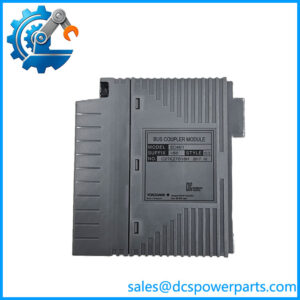
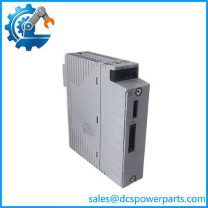
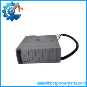
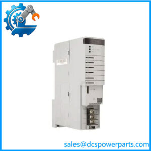
Yokogawa NFDV551-P10 Digital Output Module
The Yokogawa NFDV551-P10 is a 32-channel digital output module designed for Yokogawa STARDOM FCN/FCJ control systems. It converts controller commands into 24 VDC discrete output signals using current-sinking transistor circuits. Typical loads include solenoid valves, interposing relays, contactor interfaces, and industrial status indicators.
Its isolated output architecture supports field-device switching while separating output circuits from the controller system. The module also provides configurable HOLD and OFF fallback behavior, allowing engineers to define output responses during detected system faults. These features make it relevant to legacy controller maintenance and industrial spare-parts replacement.
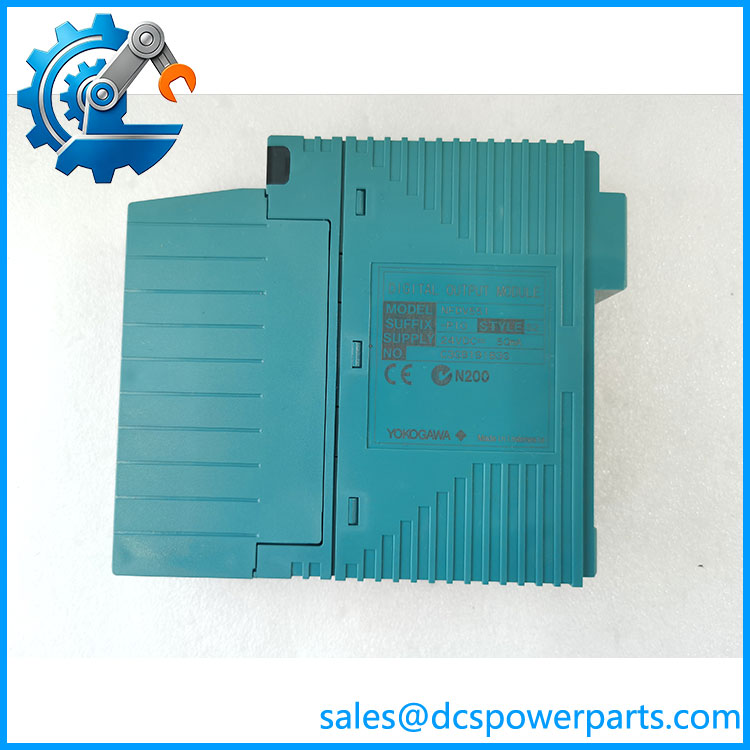
NFDV551-P10
Application Scenarios & Field Pitfalls (The Engineer’s Perspective)
Engineering Pain Point
A production line suddenly stops because several solenoid valves no longer receive their control signals. The PLC logic appears normal, but the output module has developed intermittent channel failures.
This is where a 32-channel digital output module becomes important. The provides individual discrete output points for controlling external equipment, reducing the need for multiple lower-density modules. However, engineers must check the actual load current, common wiring, and output fallback configuration before replacing the card.
Typical Applications
- Petrochemical Plants: Switching solenoid valves and auxiliary equipment in process-control sequences.
- Power Generation: Controlling relay interfaces, equipment status indicators, and auxiliary machinery.
- Water Treatment: Operating pump-start interfaces, valve actuators, and chemical dosing equipment.
- Automotive Manufacturing: Controlling pneumatic solenoids, machine interlocks, and production-line indicators.
- Industrial Process Automation: Providing discrete output commands from STARDOM FCN controllers to field equipment.
Technical Pitfalls to Avoid
1. Current-Sink Output Wiring Must Be Correct
The uses current-sinking transistor outputs (NPN). This is not interchangeable with a sourcing PNP output module.
Before installation:
- Confirm the external 24 VDC field supply polarity.
- Check the common-terminal arrangement.
- Verify that the connected load is compatible with NPN switching.
- Confirm the load current remains within the module rating.
A wiring mistake can cause outputs to remain inactive or damage connected equipment.
2. Do Not Ignore the 100 mA Channel Limit
The specified maximum load current is 100 mA per channel at 26.4 VDC. The rated load reference is 24 VDC, 50 mA.
Pay particular attention to relay coils and inductive loads. Yokogawa specifies connecting a spark-killer diode when driving DC relays.
For larger loads, use an appropriately rated interposing relay rather than connecting the load directly to the output channel.
Quick Time Engineering
3. Output Fallback Settings Can Affect Plant Operation
The supports three fallback behaviors:
- HOLD: Retains the existing output states.
- OFF: Resets all output channels to OFF.
- NO: Performs no fallback action.
The fallback detection time is approximately four seconds. The selected fallback behavior applies commonly to all channels.
This matters in process plants. A valve that should remain open during a controller fault must not unexpectedly close because a replacement module has a different fallback configuration. Verify the original application settings before commissioning.
Quick Time Engineering
Procurement and Quality Inspection
For replacement purchases, verify:
- Full model identification: -P10.
- Hardware revision and suffix markings.
- Connector type and terminal-block compatibility.
- Condition of the 50-pin connector contacts.
- Channel-by-channel output switching.
- STATUS and ACT indicator operation.
- Insulation condition and evidence of electrical testing.
For new-surplus inventory, request actual hardware photographs and test documentation. A module that powers up successfully has not necessarily passed all 32 output-channel tests.
Related Products
The following models and accessories are associated with Yokogawa STARDOM digital I/O installations.
| Model | Product Description | Compatibility and Application |
|---|---|---|
| NFDV151 | 32-channel digital input module | Complementary input module for receiving 24 VDC field status signals, push-button signals, and equipment feedback. |
| NFDV157 | 32-channel digital input module | Alternative digital input configuration using pressure-clamp terminal connections. Suitable for installations requiring direct terminal wiring. |
| NFDV557 | 32-channel digital output module | Related output module with pressure-clamp terminal configuration. Check the exact hardware suffix before considering substitution. |
| NFDV561 | 64-channel digital output module | Higher-density output alternative for applications requiring more discrete output points. Uses a different channel arrangement and connector configuration. |
| NFDV532 | 4-channel pulse-width output module | Designed for pulse-based control applications rather than ordinary 32-point ON/OFF switching. |
| NFDR541 | 16-channel relay output module | Provides relay-contact outputs for applications requiring direct switching of supported AC or DC loads. |
| NFTD5S-00 | Digital output pressure-clamp terminal block | Terminal accessory for compatible installations without the surge-absorber option. |
| NFTD5S-10 | Digital output pressure-clamp terminal block with surge absorber | Provides a surge-absorber terminal configuration for compatible installations. |
| KMS50 | 50-pin MIL connector cable | Connects compatible digital I/O modules to external terminal arrangements. Available in multiple cable lengths. |
| S9106FA | Digital output test lamp | Test accessory for checking output channels during maintenance and troubleshooting. |
Final Engineering Recommendation
The -P10 should be evaluated as a 32-channel, 24 VDC current-sinking digital output module for legacy Yokogawa STARDOM installations.
Three details deserve attention before ordering: output polarity, maximum load current, and terminal configuration. Do not substitute the NFDV557 or NFDV561 solely because they share the same digital output function. Their connector arrangements and channel capacities differ.
For procurement teams: Confirm the complete suffix, hardware revision, and terminal accessories against the existing installation. This is the most practical way to avoid receiving a physically similar module that cannot be installed directly.