Description
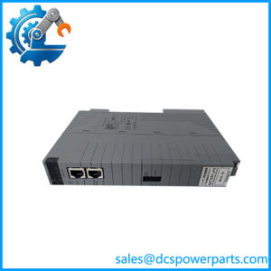
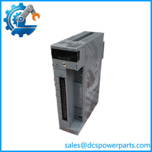
YOKOGAWA AET4D-05
Product Introduction
The Yokogawa AET4D-05 is a 16-channel thermocouple terminal board designed for Yokogawa FIO systems used with CENTUM VP. Yokogawa’s terminal-board documentation identifies the AET4D as the terminal board for thermocouple signals, with 16 channels and M4 screw terminals. The associated thermocouple input module is the AAT145, while the specified connection cable is KS1.
The Yokogawa AET4D-05 is a field termination and signal-routing component rather than the thermocouple measurement electronics itself. The AAT145 performs the temperature-input acquisition, while AET4D provides the physical interface between the field thermocouple wiring and the FIO module. This distinction is important during troubleshooting: an unstable temperature value can originate from the thermocouple, extension wiring, terminal connections, the AET4D board, the KS1 connection, or the AAT145 input circuitry. Replacing the terminal board alone does not address a failed input channel in the AAT145.
The Yokogawa -05 also incorporates reference-junction compensation hardware associated with thermocouple measurement. Yokogawa specifically warns that the terminal board should not be exposed to excessive radiated heat because the thermal environment around the terminal board affects reference-junction compensation accuracy. This makes cabinet placement and heat-source management part of the measurement accuracy consideration, not merely a mechanical installation issue.
The -05 suffix is important for procurement. Yokogawa’s ordering information identifies suffix 5 as the basic version with no explosion protection, while other suffixes provide different environmental/explosion-protection configurations.
Technical Specifications
| Parameter | Specification |
|---|---|
| Product Model | -05 |
| Manufacturer | Yokogawa Electric Corporation |
| Product Type | Thermocouple terminal board |
| System | Yokogawa FIO / CENTUM VP |
| Signal Type | Thermocouple |
| Number of Channels | 16 |
| Terminal Type | M4 screw terminals |
| Associated I/O Module | AAT145 |
| Connection Cable | KS1 |
| Redundancy | Single or dual-redundant I/O configuration |
| Reference Junction Compensation | Built into terminal-board arrangement |
| Suffix | -05 |
| Explosion Protection | Basic type, no explosion protection |
| Communication Protocol | None; passive field termination interface |
| Independent Power Supply | No |
| Measurement Conversion | Performed by associated AAT145 I/O module |
| Protection Rating | Not established as an independent IP-rated field device |
| Mounting | Yokogawa FIO cabinet/system installation |
| Weight | Approximately 1.8 kg |
| Insulation Resistance | ≥100 MΩ at 500 VDC* |
| Dielectric Strength | See Yokogawa FIO terminal-board specification* |
*General terminal-board electrical specifications should be confirmed against the applicable Yokogawa hardware revision and installation documentation. The key model-specific information—16-channel thermocouple interface, compatibility, KS1 connection, and -05 basic configuration—is directly supported by Yokogawa documentation.
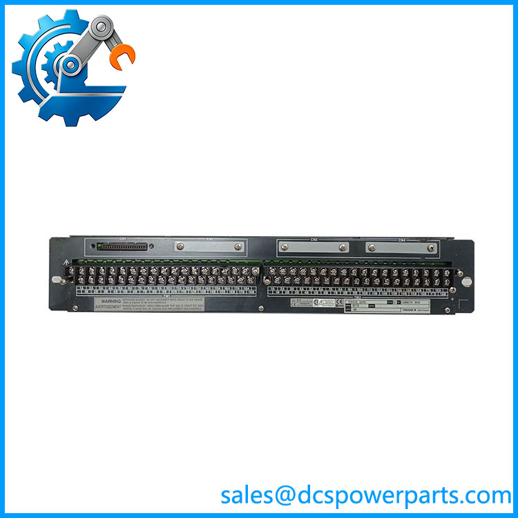
YOKOGAWA AET4D-05
Main Features and Engineering Considerations
16-Channel Thermocouple Termination
-05 provides 16 thermocouple connection points. Yokogawa lists it specifically as the terminal board for thermocouple input and associates it with the temperature-input module.
The board should therefore be viewed as part of a complete signal chain:
Thermocouple → field wiri → KS1 → → CENTUM VP
A problem anywhere along this chain can appear as an abnormal process temperature.
Reference Junction Compensation
is not simply a passive row of terminals. Yokogawa’s documentation identifies built-in reference-junction compensation associated with the arrangement. The cabinet thermal environment therefore matters.
Yokogawa specifically recommends preventing heat sources from directly affecting the terminal board. If a heat source must be positioned beside or below the board, a heat shield may be required. The reason is practical: a changing terminal-board temperature can temporarily introduce reference-junction compensation error.
Thermocouple Type and
does not independently determine the thermocouple type. Thermocouple type, scaling, burnout behavior, and related signal-processing parameters are associated with the5 and the CENTUM VP configuration.
During replacement, preserve the existing channel configuration rather than assuming that every channel can be freely reassigned without checking the engineering database.
Single and Dual Redundancy
The family is documented for single and dual-redundant module arrangements. The terminal board configuration and the way its connectors are used depend on whether the associated installation is simplex or redundant.
A replacement should therefore be checked against the actual cabinet wiring and I/O redundancy arrangement.
-05 Versus Other Suffixes
The is not simply an arbitrary revision number. Yokogawa’s ordering information identifies:
- -0: base ordering designation
- -5: basic type with no explosion protection
- -6: ISA Standard G3 option, no explosion protection
- -E: basic type with explosion protection
- -F: ISA Standard G3 option with explosion protection
For hazardous-area applications, the -05 version should not be substituted merely because the board has the same basic connector arrangement.
Application Scenarios
- Process temperature measurement
- Thermocouple field termination
- CENTUM VP FIO installations
- Refinery temperature monitoring
- Petrochemical process control
- Chemical processing
- Power-generation temperature monitoring
- Furnace and heater monitoring
- Compressor and turbine auxiliary temperature measurement
- Heat exchanger monitoring
- Legacy Yokogawa DCS maintenance
Engineer’s Guide: Field Pitfalls
1. Do not confuse with AER4D.
is for thermocouples. AER4D is for RTDs. Yokogawa identifies the two as separate terminal-board families.
2. Do not t as the input module.
The associated temperature-input module is . provides the field termination and signal interface.
3. Check cabinet heat sources.
Heat generated by nearby equipment can affect reference-junction compensation. Yokogawa specifically provides installation restrictions for / combinations.
4. Verify the suffix.
is the basic non-explosion-protected configuration. Do not substitute an explosion-protected or G3 configuration without checking the installation requirements.
5. Check KS1.
The documented connection cable between the terminal board and associated FIO hardware is KS1. Verify the installed cable and connector arrangement before replacement.
6. Inspect the field wiring.
Thermocouple polarity, correct extension-compensating cable, terminal condition, and loose connections should be checked before condemning the terminal board.
7. Allow for thermal stabilization.
After cabinet work or relocation, reference-junction accuracy can be affected while the terminal-board temperature changes. Yokogawa notes that temperature variation can introduce temporary accuracy error until the environment stabilizes.
Frequently Asked Questions
What is Yoko?
It is a 16-channel thermocouple terminal board used with Yokogawa FIO/CENTUM VP systems.
Which I/O module works ?
The documented associated module is , a Yokogawa thermocouple input module.
an analog input module?
No. It is a thermocouple terminal board. The is the associated temperature-input module responsible for signal acquisition.
How many thermocouples can it connect?
The is specified for 16 thermocouple channels.
What cable is used ?
Yokogawa documentation specifies KS1 as the connection cable for the / arrangement.
have explosion protection?
No. The -05 configuration is the basic type with no explosion protection. Yokogawa provides other suffixes for different installation requirements.
contain reference-junction compensation?
The arrangement includes built-in reference-junction compensation for the thermocouple input system. Cabinet thermal conditions therefore need to be controlled appropriately.
interchangeable with AER4D-05?
No. is for thermocouples; AER4D-05 is for resistance temperature detectors. Yokogawa’s current documentation explicitly distinguishes the two terminal-board families.
Procurement Note
Specify the component as:
Yoko — 16-Channel Thermocouple Terminal Board
For a replacement in an operating CENTUM VP system, verify the comp suffix, module, KS1 cable, simplex/dual-redundant arrangement, thermocouple wiring, and cabinet installation conditions.
The most important procurement distinction is that is a terminal board, notAT145 input electronics. If a temperature channel is malfunctioning, test the complete signal path before replacing either component. Also confirm that the non-explosion-protected -05 configuration is appropriate for the actual cabinet and plant-area classification.