Description
Technical Specifications
| Parameter | Specification |
|---|---|
| Manufacturer | Yokogawa Electric Corporation |
| Product Model | AAI543-S00 S1 |
| Product Type | Isolated analog output module |
| Number of Channels | 16 |
| Output Signal | 4–20 mA DC |
| Allowable Load Resistance | 0–750 Ω |
| Output Accuracy | ±48 µA |
| Data Update Period | 10 ms |
| Temperature Drift | ±16 µA per 10°C |
| Output-to-System Withstand Voltage | 1,500 V AC for 1 minute, subject to connection method |
| Open-Circuit Detection | Below 0.65 mA |
| Maximum Current Consumption | 230 mA at 5 V DC; 540 mA at 24 V DC |
| Redundancy | Standard switch-over response in supported redundant configurations |
| HART Communication | Not included in the standard -S version; verify the full suffix |
| Connection Options | Pressure-clamp terminal, MIL connector cable, or dedicated KS cable |
| Approximate Weight | 0.4 kg |
These values are published for the AAI543 family. The exact connection hardware and electrical isolation rating depend on the installation.
Product Overview
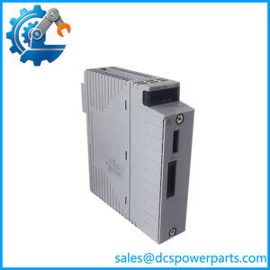
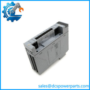
The Yokogawa AAI543-S00 S1 is an isolated analog output module designed to convert controller commands into 4–20 mA current signals for compatible distributed control system applications. With 16 output channels, it can send setpoints to field devices such as control-valve positioners, current-to-pressure converters, and other actuators that accept a standard current-loop command.
The module supports an allowable load resistance of up to 750 Ω. When evaluating a field loop, engineers should account for cable resistance, receiver input resistance, and any barriers or isolators connected in series. A load that exceeds the permitted range can prevent the output from reaching the commanded current, particularly at higher loop currents. The published output accuracy is ±48 µA, with temperature drift specified at ±16 µA per 10°C. Actual installed-loop performance also depends on calibration, wiring, environmental conditions, and the receiving device.
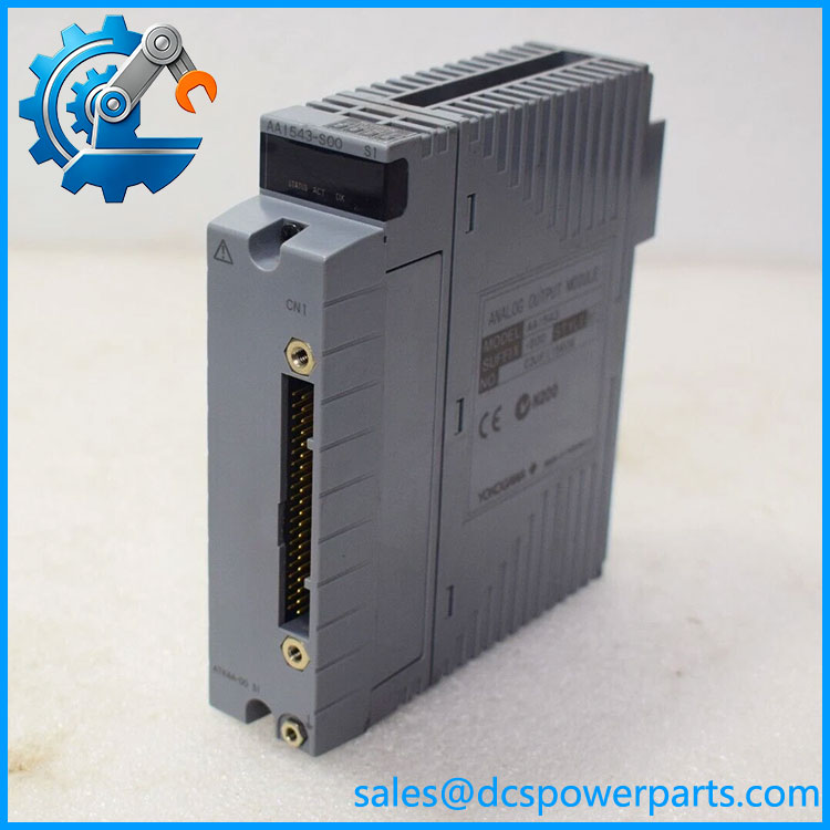
AAI543-S00 S1
The AAI543 family supports redundant configurations using two modules with matching suffix codes. In the standard switch-over configuration, the published maximum period for the field output to fall below 4 mA during a changeover is 100 ms. This transient may matter for fast-response positioners or control loops that cannot tolerate a brief reduction in output. Where the application requires faster changeover, the appropriate fast-response variant must be evaluated rather than assuming the standard module will meet the requirement.
For procurement, distinguish the manufacturer’s model code from additional supplier identifiers. The published base code is AAI543-S00; S1 appears in supplier listings but is not clearly defined as a standard Yokogawa suffix in the cited specification. Confirm the nameplate, connection arrangement, and required options before approving the unit as a replacement.
Major Features and Advantages
Sixteen isolated analog output channels
The AAI543-S00 S1 provides 16 isolated 4–20 mA output channels for controlling multiple field devices from a single I/O module position. This arrangement can simplify cabinet organization and maintenance planning in installations with many analog control loops.
Defined load capability
The allowable load resistance of 0–750 Ω gives engineers a concrete limit for loop design. Before commissioning, calculate the total load from the connected device, wiring, and intermediate components. Do not assume that every combination of positioner, isolator, and long cable run will remain within the permitted range.
Output monitoring and open-circuit detection
The specification identifies circuit-open detection below 0.65 mA. This feature can help flag a disconnected loop or another condition that prevents normal current delivery. The exact alarm behavior depends on the installed system configuration, so diagnostic indication should be checked during commissioning rather than assumed from the module specification alone.
Support for redundant output configurations
The module family supports dual-redundant operation with matching models and suffix codes. The standard switch-over response allows the control system to transfer operation to the standby module under supported conditions. A redundant pair does not eliminate every failure mode: field wiring, common power sources, output devices, and other shared components may still create single points of failure.
Defined connection and isolation requirements
The family supports several connection arrangements, including pressure-clamp terminal blocks, MIL connector cables, and dedicated cables. The specified withstand voltage between output and system is 1,500 V AC for one minute in the documented configuration; the rating can be lower with certain dedicated cable arrangements. Confirm the applicable rating for the actual terminal and cable combination.
Applications
Control-valve positioning
A 4–20 mA output is commonly used to command compatible valve positioners. The module can provide the setpoint signal, while the positioner and valve assembly perform the physical movement. During commissioning, verify current scaling, travel direction, fail position, and the response to an open or shorted loop.
Current-to-pressure converters and pneumatic actuators
The module can drive suitable current-to-pressure converters used in pneumatic control systems. Confirm the converter’s input requirements and the total loop resistance before connecting it. If the converter needs an external supply or an interposing isolator, include those components in the loop design.
Continuous process regulation
In compatible control applications, output channels can carry manipulated-variable commands for pressure, flow, temperature, or level control. The controller calculates the command; the converts it to the corresponding current output. The module itself does not perform the process-control algorithm or guarantee the accuracy of the complete control loop.
Distributed analog control panels
The 16-channel configuration can serve cabinets that consolidate several analog final-control signals. The selected terminal block, cable interface, and field wiring arrangement should be documented for each channel. This is especially important in retrofit projects where the original cabinet may use connection accessories that are not included with a replacement module.
Redundant control applications
Where output continuity is important, a compatible redundant configuration may reduce the effect of a single module failure. Engineers should verify whether the standard switch-over response is acceptable for the field device and control-loop dynamics. If a brief output drop could cause a trip, unwanted actuator movement, or a process upset, evaluate the appropriate fast-response version and test the actual changeover behavior.
Related Products
| Model | Function |
|---|---|
| -S00 | Base 16-channel isolated analog output module |
| -H | HART-capable variant; verify the complete model and suffix |
| AAI143-S00 | 16-channel isolated 4–20 mA analog input module |
| AAI141 | 16-channel non-isolated analog input module |
| AAI135 | 8-channel isolated analog input module |
| AAI835 | Combined analog input/output module |
| ATA4S-00 | Pressure-clamp terminal block for compatible analog I/O |
| ATA4D-00 | Dual pressure-clamp terminal block for compatible analog I/O |
| ATK4A-00 | KS cable interface adapter for compatible analog I/O connections |
These products are related members of the Yokogawa analog I/O family or associated connection hardware. Their signal direction, channel count, communication capability, and interface requirements differ; they are not automatic replacements for the -S00 S1.
Installation and Maintenance
Before replac S1, verify the complete nameplate code and compare it with the site’s bill of materials. Follow the approved isolation procedure and the applicable Yokogawa installation instructions. Do not assume that a supplier’s additional S1 designation proves hardware equivalence.
Inspect the module, connector, and terminal assembly for damaged contacts, contamination, loose wiring, or signs of overheating. Confirm the correct cable and terminal accessories, then check the wiring polarity and channel assignment against the control drawings. Calculate the loop’s total resistance and ensure it remains within the specified 750 Ω maximum.
After installation, verify that the control system recognizes the module and that each affected channel reports normal status. Use an approved loop calibrator or test arrangement to check representative output values across the operating range. Confirm that the receiving device responds correctly and that the output scaling matches the control-system configuration. For redundant installations, perform the documented changeover test and assess any transient at the field device before returning the loop to normal operation.
Record the installed model, hardware identification, channel test results, and any changes to the terminal or cable arrangement. If the application depends on a fast redundant transfer, confirm the switch-over response specification before accepting a standard-response replacement.
Product Assurance
For procurement of the Yok S1, verify the exact product identity, connection arrangement, physical condition, and test documentation. The model-family specification establishes the expected analog output characteristics but does not establish the condition or service history of an individual unit.
Request a clear photograph of the nameplate and confirmation of the full ordering code. Ask the supplier to explain the S1 designation and identify any included terminal blocks, adapters, or cables. If the proposed unit has a different suffix, obtain documented confirmation that it meets the installed system’s requirements.
Where functional testing is offered, clarify whether the test covers output-current accuracy, all required channels, open-circuit detection, and redundant changeover where applicable. A visual inspection alone cannot demonstrate correct current output under load. For critical loops, compare the test scope with the site’s acceptance criteria.
Finally, confirm the supplied condition, warranty terms, traceability records, and delivery schedule for the actual unit being quoted. This provides a clearer basis for replacement approval than relying on a catalog title or a broadly similar model number.