Description
Technical Specifications
| Parameter | Specification |
|---|---|
| Model | AAI143-S00 |
| Manufacturer | Yokogawa |
| Module type | Isolated analog input |
| Number of channels | 16 |
| Input signal | 4–20 mA DC |
| Maximum allowable input current | 24 mA |
| Input resistance, powered | Approximately 270 Ω at 20 mA to 350 Ω at 4 mA |
| Input resistance, power off | 500 kΩ or greater |
| Stated accuracy | ±16 µA |
| Data update period | 10 ms |
| Input-to-system withstand voltage | 1,500 V AC for 1 minute under the specified connection conditions |
| Transmitter supply | 19.0 V minimum at 20 mA; 25.5 V maximum at 0 mA |
| Transmitter supply current limit | 25 mA |
| Power consumption | Maximum 230 mA at 5 V DC and 540 mA at 24 V DC |
| Supported transmitters | Two-wire or four-wire, selected per channel |
| External connection | Pressure-clamp terminal, MIL connector cable, or dedicated KS1 cable |
| Approximate weight | 0.3 kg |
| HART communication | Do not assume HART support for this standard version; verify the applicable system and module documentation |
Specifications are based on published AAI143 family data. The stated withstand voltage can be lower when a dedicated cable is used, so check the connection method before applying insulation-test procedures.
Product Overview
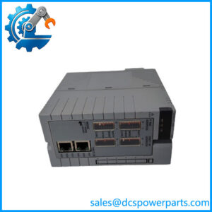
The Yokogawa AAI143-S00 is a 16-channel isolated analog input module designed for industrial distributed control systems. It acquires standard 4–20 mA DC signals from field instruments and makes the measured values available to the control system for monitoring, alarms, and process control. Typical signals include pressure, flow, level, and temperature measurements supplied by compatible transmitters with current-loop outputs. Yokogawa documentation lists the AAI143 as an isolated 4–20 mA analog input module for FIO-related system configurations.
The module supports two-wire and four-wire transmitter connections, with the selection made separately for each channel using the designated setting pin. Its stated accuracy is ±16 µA, and its data update period is 10 ms. These figures are useful when evaluating signal acquisition requirements, but they should not be interpreted as a guarantee of total measurement-loop accuracy. Transmitter calibration, wiring resistance, grounding, signal noise, and control-system scaling can all affect the value ultimately displayed by the operator station.
The AAI143-S00 must be matched to the installed Yokogawa node and terminal arrangement. Supported connections include pressure-clamp terminals, MIL connector cables, and the dedicated KS1 cable, subject to the applicable assembly. Input-to-system isolation and the specified withstand voltage also depend on the connection conditions. Before replacement, confirm the full model code, terminal hardware, node compatibility, and required configuration. Do not substitute a non-isolated analog input module simply because it accepts the same nominal current signal.
Major Features and Advantages
16-channel current-loop acquisition
The AAI143-S00 provides 16 analog input channels for standard 4–20 mA DC signals. This channel density can reduce the number of separate modules needed for a cabinet containing multiple process measurements. The allowable input current is specified at 24 mA, giving the module a defined operating limit beyond the nominal 20 mA upper measurement value.
Isolated analog input design
The module is classified as an isolated analog input module. Isolation helps manage electrical differences between field signal circuits and the control-system side. However, the exact isolation boundaries and applicable withstand ratings must be interpreted from the manufacturer’s documentation; the published 1,500 V AC rating is specified for input-to-system withstand testing under defined conditions. A dedicated cable can change the applicable rating, so do not assume the same value applies to every wiring arrangement.
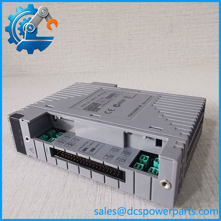
AAI143-S00
Support for two-wire and four-wire transmitters
Each channel can be configured for the applicable transmitter connection method. This is useful in installations where instruments have different power arrangements. Before connecting a transmitter, check its wiring diagram, loop supply requirements, polarity, and the module’s channel setting. An incorrect configuration can cause an invalid reading or prevent the loop from operating as intended.
Defined acquisition performance
The specified ±16 µA accuracy and 10 ms update period provide useful reference points for engineering reviews and fault investigations. The update period describes the module’s data refresh behavior, not the complete response time of the control loop. Controller execution, communication scheduling, filtering, and operator display updates may add further delay. The module should therefore be assessed as one component of the complete measurement chain.
Flexible terminal and cable arrangements
The documented external connection options include pressure-clamp terminals, MIL connector cables, and a dedicated KS1 cable. The correct option depends on the installed terminal assembly and cabinet design. Verify the connection hardware before ordering: a compatible module may still require the correct terminal block, cable, or adapter to complete the installation.
Redundant-system integration
The family is documented for use in dual-redundant configurations where supported by the host system. Redundancy requires the appropriate module pairing, slot arrangement, system configuration, and compatible hardware. Confirm the applicable installation manual before replacing a module in a redundant pair; physical fit alone does not establish correct redundancy behavior.
Applications
Process measurement in distributed control systems
The -S00 is suitable for acquiring standard current-loop signals from instruments used in process monitoring and control. Examples include pressure transmitters on pipelines, flow transmitters on process lines, and level transmitters on storage vessels. The control system can use these values for operator displays, alarm thresholds, trend recording, and control strategies configured for the application.
Chemical and petrochemical facilities
Chemical plants often use 4–20 mA loops to communicate process measurements between field instruments and distributed I/O. The module’s 16-channel format supports multiple measurements within a defined node configuration. Isolation can be relevant where electrical potential differences or signal interference need to be managed, but hazardous-area suitability must be assessed separately. The basic model designation should not be treated as evidence of explosion protection or intrinsic-safety approval.
Power generation and utility systems
Power generation facilities use analog transmitters to monitor pressures, flows, tank levels, and auxiliary-system conditions. A compatible -S00 can acquire these signals for the associated Yokogawa control system. When used in a critical measurement loop, engineering teams should verify scaling, loop power, transmitter wiring, alarm limits, and redundancy requirements before returning the channel to service.
Water treatment and industrial utilities
Water treatment, cooling-water, and plant utility systems commonly use 4–20 mA transmitters for flow, pressure, and level monitoring. The module can support these measurements when installed in an approved Yokogawa system configuration. Signal quality still depends on field wiring, shielding practices, transmitter condition, and correct configuration at both the module and controller levels.
Maintenance and fault replacement
During troubleshooting, an incorrect process reading does not necessarily indicate a failed analog input module. Check the transmitter output, loop current, terminal connections, channel settings, system scaling, and diagnostics before replacing hardware. If the module is confirmed defective, a correctly configured replacement can restore the input function, provided the terminal arrangement and system compatibility are also verified.
Related Products
The following models are related to Yokogawa’s analog I/O and control-system hardware. They have different signal types or functions and are not automatically interchangeable.
| Model | Relationsh |
|---|---|
| -H00 | Related version with HART digital communication capability; verify the exact ordering code and system support. |
| AAI141 | 16-channel 4–20 mA analog input module in a non-isolated configuration. |
| AAI135 | Eight-channel isolated 4–20 mA analog input module. |
| AAI543 | 16-channel isolated 4–20 mA analog output module. |
| AAI835 | Analog I/O module with four inputs and four outputs for supported configurations. |
| AAV144 | 16-channel voltage input module for its specified voltage range. |
| AAT145 | Thermocouple and millivolt input module for supported sensor types. |
| ATA4S-00 | Pressure-clamp terminal block accessory for compatible analog modules. |
| ATA4D-00 | Dual pressure-clamp terminal block accessory for supported installations. |
The module functions and channel counts are identified in Yokogawa’s published I/O documentation. Confirm the suffix, terminal accessories, host node, and system revision before choosing a related product as a replacement.
Installation and Maintenance
Before installin, verify the complete part number and confirm that the receiving Yokogawa node supports the module. Check the installed terminal block or cable type, the required channel settings, and whether the application uses a redundant configuration. Follow the plant’s isolation and electrical safety procedures before removing or inserting hardware.
For each connected transmitter, verify whether the circuit is two-wire or four-wire and configure the corresponding channel setting as specified by Yokogawa. Confirm polarity, wiring continuity, loop current, and transmitter supply requirements. The module’s documented transmitter supply characteristics should not be treated as a substitute for checking the transmitter’s own voltage and current requirements.
During troubleshooting, compare the field loop current with the value reported by the control system. Inspect terminals and connectors for loose contacts, corrosion, contamination, or damage. If a channel reading is incorrect, check transmitter calibration, cable condition, channel configuration, and controller scaling before concluding that the input module has failed.
Take particular care when performing insulation testing. The specified input-to-system withstand voltage is conditional on the connection method; a dedicated cable may have a lower applicable rating. Do not apply a test voltage without checking the manufacturer’s procedure for the installed hardware.
After replacement, verify all affected channels against known process values or an approved current-loop test source. Confirm that scaling, alarm thresholds, and diagnostics are correct before handing the equipment back to operations. Record the replacement model, test results, and any unresolved measurement discrepancies in the maintenance log.
Product Assurance
For procureme, verify the complete model designation, terminal arrangement, and compatibility with the existing Yokogawa control-system configuration. Published technical specifications establish the module’s general function and electrical characteristics, but they do not establish the condition or testing history of a specific unit being supplied.
Recommended incoming checks include:
- Part-number verification: Co against the purchase order and approved spare-parts list.
- Physical inspection: Check the connector, housing, label, and module contacts for damage or alteration.
- Configuration review: Confirm the required terminal block or cable and the supported host node.
- Functional testing: Request documented test results for channel acquisition, current-loop response, and relevant diagnostics.
- Condition disclosure: Obtain written confirmation of whether the supplied unit is new, used, or refurbished.
- Compatibility confirmation: Verify the intended slot, redundancy arrangement, and applicable system revision.
For critical process measurements, a replacement should be accepted on the basis of correct configuration and documented test evidence rather than appearance alone. Confirm warranty terms and return conditions before dispatch, and retain the incoming inspection records with the plant’s maintenance documentation.