Description
Woodward WIP11I1E1 Self-Powered Time Overcurrent Relay
Product Introduction
The Woodward WIP11I1E1 is a WIP1-1 self-powered time overcurrent relay designed for electrical protection systems where dependable overcurrent and earth-fault protection is required without relying on a conventional auxiliary control-power source. The WIP1 derives its operating energy from the current-transformer circuits and can provide the tripping energy required by the circuit breaker. This makes the relay suitable for switchboards and generator protection arrangements where protection availability must be maintained even when auxiliary voltage is lost. Woodward documentation identifies WIP11 as one of the WIP1 hardware versions and specifies phase overcurrent, short-circuit, earth-fault overcurrent, and earth short-circuit protection functions.
The Woodward WIP11I1E1 is specifically associated with a 1 A rated-current configuration and additional earth-current measurement. The protection structure includes I> and I>> phase-current elements together with IE> and IE>> earth-current elements. Definite-time or inverse-time characteristics can be selected for the applicable protection stages. The relay can trip through an electrical pulse output directly associated with the breaker trip circuit or through potential-free relay contacts. The WIP1 manual specifies repeated trip pulses at 150 ms intervals until the circuit breaker is switched off when the electro-pulse method is selected.
For procurement, the Woodward WIP11I1E1 should be matched by its complete ordering code rather than simply by the WIP1 family designation. WIP1-1, -2, and -3 have different hardware arrangements. The -3 version can include RS-485 communication, while WIP11 is the non-communications -1 configuration. The documented -1 software version is V02-1.12, which is another useful identification point when inspecting an installed or refurbished relay.
Technical Specifications
| Parameter | Specification |
|---|---|
| Manufacturer | Woodward |
| Model | WIP11I1E1 |
| Product Family | |
| Hardware Version | -1 / WIP11 |
| Product Type | Self-powered time overcurrent relay |
| Rated Current | 1 A |
| Measuring Supply | Derived from CT circuits |
| Phase Overcurrent | I> |
| High-Set Short Circuit | I>> |
| Earth-Fault Overcurrent | IE> |
| Earth High-Set Protection | IE>> |
| Earth Current Measurement | Included |
| Overcurrent Characteristic | Definite-time / inverse-time |
| Earth-Fault Characteristic | Definite-time / inverse-time |
| Trip Method | Electrical pulse or potential-free relay |
| Auxiliary Supply | Not required for self-powered operation |
| RS-485 | Not part of -1 / WIP11 configuration |
| Modbus RTU | Not applicable te configuration |
| Fast Trip Input | Available through external signal input |
| External Reset | Supported |
| Blocking Inputs | Supported |
| Display | LCD |
| Fault Memory | Supported |
| Self-Supervision | Watchdog/self-monitoring |
| Documented WIP11 Software | V02-1.12 |
| Typical Default I> Pickup | 0.5 A |
| Typical Default I>> Pickup | 1.0 A |
| Typical Default IE> Pickup | 0.05 A |
| Typical Default IE>> Pickup | 0.1 A |
| Default Overcurrent Delay | 0.06 s |
| Default Earth-Fault Delay | 0.06 s |
The pickup and delay values above are factory/default settings documented in the manual, not recommended operating settings. Actual settings must be taken from the relay’s configuration record and the site’s protection study.
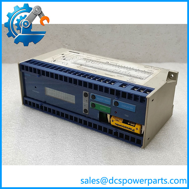
Woodward WIP11I1E1
Main Features and Engineering Considerations
CT-Powered Operation
The defining characteristic of the platform is self-powered operation. The relay obtains its operating energy from the CT circuits rather than requiring a separate auxiliary supply for its basic operation. The documentation also distinguishes the relay’s own operating supply from the energy used to generate the breaker trip pulse. This distinction matters when evaluating CT performance and the breaker trip circuit.
1 A CT Configuration
The I1 designation is important because this version is configured for a 1 A rated current. A 1 A protection relay should not be substituted into a 5 A CT secondary circuit without confirming the complete protection arrangement. CT ratio, secondary wiring, burden, polarity, and shorting arrangements all need to be checked before commissioning.
Phase and Earth-Fault Protection
The protection structure includes four principal elements: I> for phase overcurrent, I>> for high-set short-circuit protection, IE> for earth-fault overcurrent, and IE>> for high-set earth-fault protection. The exact enabled/tripping behavior is configurable. The manual shows these elements as available in the WIP11 configuration.
Definite-Time and Inverse-Time Protection
The relay supports selectable protection characteristics, including definite-time and inverse-time behavior. This allows the WIP11I1E1 to be coordinated with upstream and downstream protective devices. Settings should be reproduced from the approved protection study rather than copied from generic documentation.
Direct Breaker Trip Capability
The provides two documented tripping approaches. An electrical pulse can be delivered directly to the circuit-breaker trip coil, or potential-free relay contacts can be used where a separate trip circuit is required. The electrical pulse is repeated every 150 ms until the breaker switches off.
No Communication
One important distinction is the absence of the RS-485 communication option oe / configuration. Woodward identifies RS-485 with -3. Therefore, if the existing protection relay is connected to a SCADA system through RS-485, should not be assumed to be a functional communications-equivalent replacement.
Application Scenarios
- Generator overcurrent protection
- Generator earth-fault protection
- Industrial switchgear
- Feeder protection
- Electrical distribution panels
- Power-generation auxiliary systems
- Circuit-breaker protection
- Switchboards without dedicated auxiliary relay power
- Legacy Woodward protection installations
- Industrial plants requiring CT-powered protection
Engineer’s Guide: Field Pitfalls
1. Verify the 1 A CT secondary.
The is a 1 A configuration. Do not replace it with a 5 A version simply because both devices belong to the family.
2. Confirm earth-current measurement.
The E1 configuration is associated with additional earth-current measurement. Removing this function can change the protection coverage even if phase overcurrent protection continues to work.
3. Do not assume RS-485.
-3 provides the communication interface op. / does not provide the same communications capability.
4. Preserve the protection settings.
The manual’s default settings are only starting values. Actual pickup currents, time delays, inverse curves, high-set thresholds, and earth-fault settings must be recorded from the installed relay or approved protection documentation before replacement.
5. Check the trip-coil arrangement.
If the installation uses the electrical pulse output, verify the breaker trip-coil characteristics and relay terminal wiring before commissioning. The relay can also use potential-free contacts, so the actual configuration needs to be confirmed.
6. Check the software revision.
Woodward docus software version V02-1.12 in the referenced manual. When dealing with an older or refurbished unit, compare the nameplate and internal software/version information against the existing relay.
7. Do not confuse with -I1.
The shorter -I1 designation appears in some inventory listings, while the complete ordering code identifies a more specific configuration. For procurement, use the complete nameplate code whenever available.
Frequently Asked Questions
What is Woodward ?
Woodward a self-powered time overcurrent relay with a 1 A rated-current configuration and additional earth-current measurement. It provides phase overcurrent, high-set short-circuit, earth-fault, and high-set earth-fault protection functions.
Is self-powered?
Yes. The is designed to obtain its operating power from the CT circuits, eliminating the need for a conventional auxiliary supply for its basic self-powered operation.
What is the rated current of ?
The I1 configuration is rated for 1 A CT input. This is a critical replacement parameter.
Does support Modbus?
No. / configuration does not have the RS-485 communication option. Woodward identifies the RS-485 interface with the -3 configuration, where Modbus RTU or Woodward-Pro Open Data Protocol can be selected.
Does provide earth-fault protection?
Yes. The documentation shows IE> and IE>> earth-current protection functions for .
Can directly trip a breaker?
Yes. The can use an electrical pulse output to operate the circuit-breaker trip coil. It can also use potential-free relay contacts depending on the configured tripping method.
Is a generator controller?
No. It is an electrical protection relay. Its primary role is current-based protection and breaker tripping, not generator speed control, excitation control, or engine control.
Procurement Note
Specify the item as:
Woodwa— — 1 A CT-powered self-powered time overcurrent relay with earth-current measurement.
Before accepting a replacement, verify the complete code, revision, 1 A CT input, earth-current function, trip-output arrangement, existing protection settings, terminal configuration, and software revision.
The most important point is not the physical appearance of the relay. The family contains multiple configurations, and Woodward explicitly distinguishes , WIP12, and WIP13 in its documentation. A replacement that looks like a but has the wrong CT rating, earth-current arrangement, or communication configuration can create a protection-system mismatch.