Description
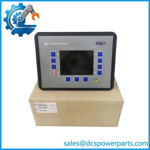
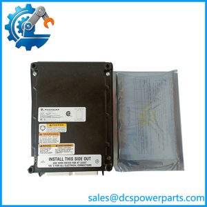
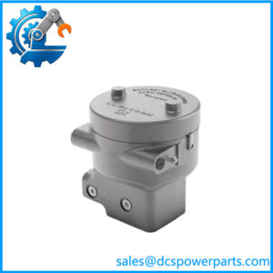
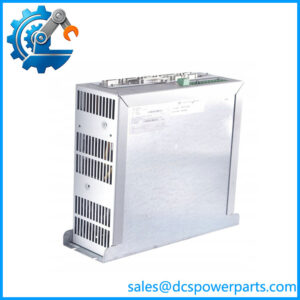
Woodward 8800-1001 DSS-2 — Two-Channel Digital Speed Switch
Product Overview
The Woodward 8800-1001 DSS-2 is a two-channel digital speed switch designed to monitor rotating machinery and provide discrete relay switching at configured speed thresholds. It is used in engine and other rotating-equipment applications where speed monitoring supports alarms, interlocks, or shutdown logic. Unlike a full engine governor, the DSS-2 is primarily a speed-switching device: its relay outputs change state according to the configured switching conditions rather than continuously regulating engine speed.
The unit operates from a 9–30 VDC supply and includes reverse-polarity protection. Its two channels provide separate speed-switch functions, while the relay contacts can interface with compatible control or protection circuits. Published specifications list relay contact ratings of 1–10 A for resistive loads and 1–8 A for inductive loads at 28 VDC. These are load-dependent limits, not a blanket rating for every connected device. Relay switching duty, inrush current, suppression, wiring, and the receiving circuit’s requirements must all be considered when designing or verifying the installation.
For maintenance teams, Woodward 8800-1001 is relevant when a legacy speed-switch function must be restored without changing the surrounding control design. The model is listed as a replacement for the earlier SA-1905, but the installed wiring and configured trip points still require verification. Before commissioning a replacement, confirm the magnetic pickup signal, power supply, channel settings, relay logic, and the downstream circuit response. The unit’s compact, encapsulated construction and Euro-style terminal block simplify panel integration, but they do not eliminate the need for functional testing. Because supplier records indicate that the product may be discontinued, procurement teams should also establish the actual stock condition and availability of technical support before committing to a critical spare.
Product Introduction (Non-Templated)
A speed switch may be a small component, but its relay outputs can initiate significant actions in an engine or rotating-equipment protection circuit. The Woodward 8800-1001 DSS-2 provides two independent speed-switch channels with a 9–30 VDC supply range.
For replacement work, the critical checks are the pickup signal, configured switching thresholds, relay contact arrangement, and downstream trip logic. Verify the complete circuit before returning the equipment to service.
Key Technical Specifications
| Parameter | Specification |
|---|---|
| Manufacturer | Woodward |
| Model | 8800-1001 |
| Product Designation | DSS-2 |
| Product Type | Two-channel digital speed switch |
| Primary Function | Rotational-speed monitoring and relay switching |
| Power Input | 9–30 VDC |
| Reverse-Polarity Protection | Yes |
| Operating Channels | 2 |
| Speed Sensor | Compatible magnetic pickup (MPU); verify sensor requirements |
| Relay Configuration | Relay outputs; confirm exact contact wiring against the manual |
| Relay Rating, Resistive Load | 1–10 A at 28 VDC |
| Relay Rating, Inductive Load | 1–8 A at 28 VDC |
| Termination | Euro-style terminal block |
| Operating Temperature | −40°C to +85°C |
| Weight | Approximately 0.17 kg (0.38 lb) |
| Housing | Encapsulated housing; published documentation identifies UV- and chemical-resistant material |
| Calibration | Manual or using the compatible All-purpose Calibration Tool (ACT) |
| Associated Tool Reference | SA-5206, listed for ACT |
| Replacement Reference | SA-1905 |
| Manufacturer Status | Some distributors report the model as discontinued; confirm directly before procurement |
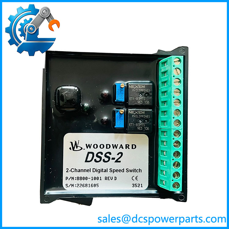
8800-1001
Related Products
These items support identification, maintenance, or integration of the DSS-2. They are not all interchangeable with the 8800-1001.
- Woodward SA-1905 — Earlier speed-switch part number listed as replaced by the 8800-1001. Verify the approved replacement documentation and terminal compatibility.
- Woodward Magnetic Pickup (MPU) — Provides the speed signal used by compatible speed-switch systems. Confirm pickup characteristics, mounting, air gap, and signal quality.
- Woodward SA-5206 ACT — All-purpose Calibration Tool reference associated with speed-switch calibration. Check the applicable instructions and tool compatibility.
- Woodward 9905 Series Controls — Separate Woodward control products that may appear in broader engine or turbine control systems. They are not direct substitutes for the .
- Woodward 505 Series Controls — Turbine control systems with a different control role and architecture. Use only where the plant design specifically calls for that platform.
- Speed-Switch Relay Circuit — The downstream alarm, interlock, or shutdown circuit must be checked against the contact arrangement and load rating.
- Engine or Turbine Overspeed Protection System — A system-level protection function that may use speed-switch outputs. Confirm the required safety architecture and do not assume the alone provides a complete independent overspeed protection system.
Frequently Asked Questions
Q1. What is the Woodward 8800-1001 used for?
It monitors rotational speed and switches relay outputs when configured speed conditions are met. Typical uses include speed alarms, interlocks, and control or protection actions on compatible rotating equipment.
Q2. Does the have two independent channels?
Yes. The product is specified as a two-channel digital speed switch. Confirm the individual channel settings and how each relay is wired into the installed control or protection circuit.
Q3. What power supply does the 8800-1001 require?
The published input range is 9–30 VDC, with reverse-polarity protection. Check the supply voltage at the device terminals under operating conditions and follow the manufacturer’s wiring instructions.
Q4. Can the relay outputs directly operate a shutdown solenoid?
That depends on the solenoid’s voltage, steady-state current, inrush current, inductive characteristics, and the applicable relay rating. The published inductive-load rating is lower than the resistive-load rating. Use an appropriately rated interposing relay or driver when required by the circuit design.
Q5. Is the 8800-1001 a direct replacement for SA-1905?
Supplier references list the 8800-1001 as replacing SA-1905. Before installing it, confirm the replacement relationship using the applicable Woodward documentation, then compare wiring, sensor requirements, switching thresholds, and relay behavior.
Q6. Can I hot-swap the ?
Do not assume live replacement is permitted. Isolate the device and associated circuits according to the equipment manufacturer’s instructions and site lockout/tagout procedures. Verify the downstream circuit’s safe state before removing or reconnecting the switch.
Q7. How should I test a replacement unit before returning equipment to service?
Verify supply voltage, magnetic-pickup signal quality, channel settings, relay contact state, and the complete downstream response. Test the required switching thresholds using an approved procedure and suitable test equipment. Record the results; do not rely solely on a power-on check or visual inspection.
Q8. What should I verify when purchasing surplus stock?
Confirm the exact 8800-1001 part number, actual stock condition, terminal integrity, and available functional-test evidence. Ask whether the unit has been calibrated and whether warranty or return coverage applies. If the equipment is safety-critical, obtain engineering approval and validate the complete protection circuit before use.