Description
Key Technical Specifications
| Parameter | Value |
|---|---|
| Manufacturer | GE Fanuc / VME Systems |
| Model | VMIVME-1128 |
| Product Type | Digital Input VME Module |
| Bus Standard | VMEbus |
| Board Format | 6U VME |
| Input Channels | 32 isolated digital inputs |
| Input Type | Optically isolated discrete inputs |
| Input Voltage Range | 24 VDC / 48 VDC industrial signal levels |
| Isolation Method | Optical isolation between field and logic circuits |
| Data Transfer | VMEbus D16 access |
| Addressing | A16/A24 selectable |
| Interrupt Support | VME interrupt capability |
| Input Filtering | Hardware input filtering for noise suppression |
| Field Connection | Front panel / rear transition interface depending on configuration |
| Operating Temperature | Industrial temperature range |
| Mounting | Standard VME chassis slot |
| Cooling | Forced-air VME rack cooling |
| Application | Industrial discrete signal monitoring |
Product Introduction
GE VMIVME-1128 Overview
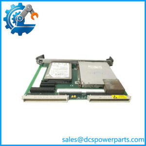
The GE VMIVME-1128 is a 6U VMEbus digital input module designed for industrial and embedded control applications requiring reliable acquisition of discrete field signals. It provides a direct interface between external electrical devices and a VME-based control computer, allowing legacy automation platforms to monitor equipment status, interlocks, alarms, and machine operating conditions.
The GE VMIVME-1128 uses optically isolated input channels to separate field wiring from the VME processor electronics. This design reduces the risk of electrical noise, voltage transients, and ground potential differences affecting the embedded controller. The module is suited for industrial environments where signals originate from remote sensors, switches, relay contacts, and other field devices.
The GE VMIVME-1128 integrates into VME control architectures as an I/O expansion board controlled by a host VME CPU. It is commonly installed alongside VME processor boards, analog input modules, communication cards, and specialized IndustryPack carriers in long-life automation systems. The board provides discrete input acquisition without requiring external signal conversion hardware for many industrial voltage levels.
The VMIVME-1128 is typically found in systems where VME technology remains in operation due to long equipment life cycles, validated software environments, and the cost associated with control system redesign. Applications include industrial machinery, automated test platforms, transportation equipment, and specialized embedded controllers.
Before replacement, engineers should verify input voltage levels, connector wiring, VME addressing, interrupt configuration, and the software driver or application mapping. A physically compatible VME board may still require configuration updates before returning the system to operation.
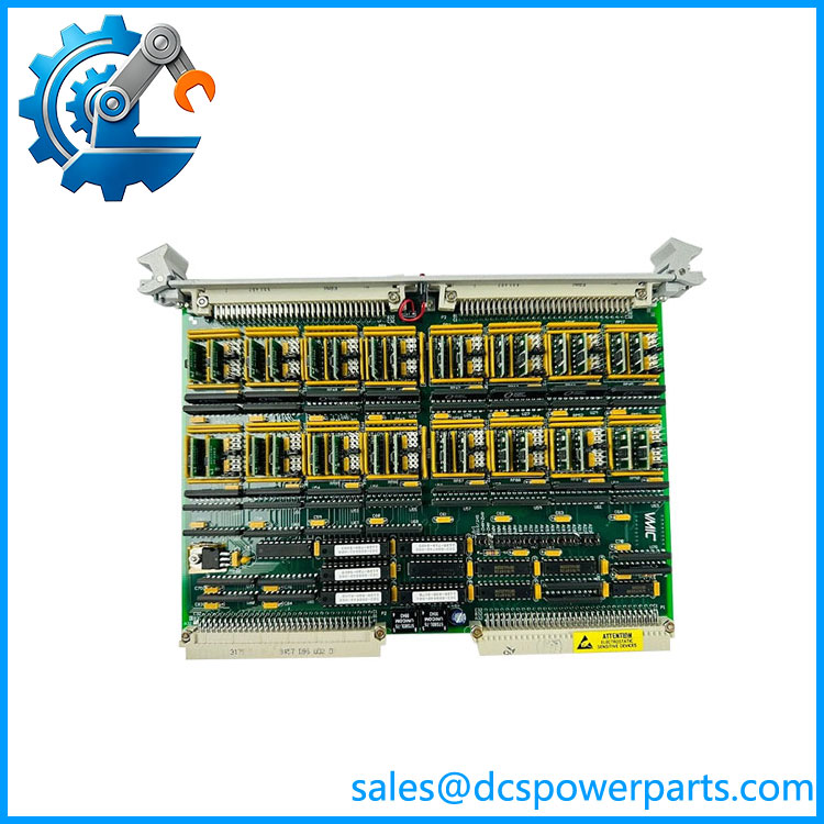
VMIVME-1128
Application Scenarios & Field Pitfalls (The Engineer’s Perspective)
Engineering Pain Point
A legacy VME control system reports missing status signals, incorrect interlock conditions, or inconsistent digital inputs. The I/O module may be suspected, but field wiring, sensor power supply, and configuration errors are common causes.
Recommended troubleshooting steps:
- Check module status indicators
- Measure field input voltage levels
- Verify input polarity
- Inspect terminal wiring
- Confirm VME address settings
- Review application I/O mapping
The provides the digital acquisition interface, but reliable operation depends on the complete field signal path.
Typical Applications
Industrial Automation Systems
Used for:
- Machine status monitoring
- Safety interlocks
- Limit switch monitoring
- Sequence control inputs
Power and Utility Equipment
Applied for:
- Breaker status monitoring
- Alarm inputs
- Equipment condition signals
Automated Test Equipment
Used for:
- Test fixture monitoring
- Device status acquisition
- Control sequencing
Transportation and Embedded Systems
Applied for:
- Vehicle monitoring
- Control cabinet I/O
- Legacy embedded platforms
Technical Pitfalls to Avoid
1. Verify Field Voltage Compatibility
Before installation, confirm:
- Input voltage level
- Signal polarity
- Sensor output type
- Current requirements
Applying incorrect field voltage can damage input circuitry.
2. Check VME Configuration
Review:
- Board address settings
- Interrupt configuration
- VME slot requirements
- CPU software mapping
The module must match the original VME system configuration.
3. Inspect Field Wiring
Common issues include:
- Loose terminals
- Broken signal cables
- Incorrect common connections
- Grounding problems
Optical isolation protects the board, but it cannot correct incorrect field wiring.
4. Preserve Application Configuration
Record:
- Input channel assignments
- Alarm definitions
- PLC/VME software mappings
- System documentation
Replacing hardware without restoring software configuration may produce incorrect machine behavior.
Related Products
- GE VMIVME-1126
Related VME digital input module family for industrial discrete signal acquisition. - GE VMIVME-1130
VME digital output module used for actuator and relay control applications. - GE VMIVME-1150
High-density digital I/O module used in VME automation systems. - GE VMIVME-3122
Analog input VME module for process measurement applications. - GE VMIVME-7807
VME single-board computer commonly used as a host processor in VME-based control systems.