Description
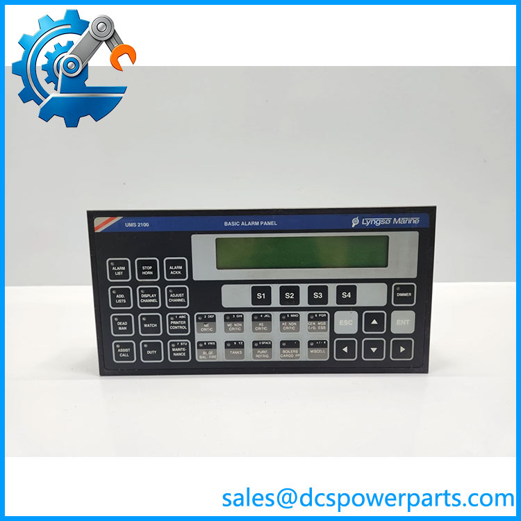
Lyngsø Marine UMS2100 Universal Alarm and Monitoring System
Key Technical Specifications
| Parameter | Specification |
|---|---|
| System designation | UMS2100 |
| Manufacturer / system origin | Lyngsø Marine / STX-Lyngsø Marine |
| Application | Marine machinery alarm and monitoring |
| System type | Distributed, modular monitoring system |
| Operator interface | Basic alarm panels and optional extended alarm displays |
| Remote acquisition | Outstations with configured I/O channels |
| Binary inputs | Project-dependent |
| Binary outputs | Project-dependent |
| Analog inputs | Project-dependent; documented configurations include 4–20 mA, 0–10 V, and selected temperature sensor inputs |
| Analog outputs | Depends on the installed system configuration; one documented project lists none |
| Serial communication | Interfaces depend on installed hardware and system configuration |
| Network architecture | Project-specific; some documented systems support redundant alarm-panel networks |
| Alarm presentation | Audible and visual indications, with text-based alarm presentation on applicable panels |
| Software | UMS2100 system software; version and operating environment depend on the installation |
| Power requirements | Verify each panel, processing unit, and outstation nameplate |
| Environmental ratings | Verify for each installed assembly |
| Replacement compatibility | Requires confirmation of system version, hardware type, I/O mapping, and configuration files |
The I/O details above are examples from published UMS2100 project documentation, not universal ratings for every installation. For instance, one documented vessel configuration lists 224 binary inputs, 16 binary outputs, 112 analog inputs, and zero analog outputs. These values must not be assumed for another vessel.
Product Introduction
The Lyngsø Marine UMS2100 is a universal alarm and monitoring platform designed for marine machinery applications. It gathers signals from distributed equipment and presents alarms and operating information at designated shipboard stations. Depending on the vessel’s design, the installation may include basic alarm panels, extended displays, remote outstations, processing computers, and communication interfaces. Its configuration is determined by the vessel-specific system design rather than a single standard module specification.
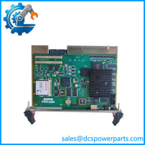
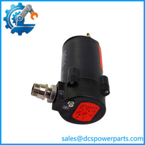
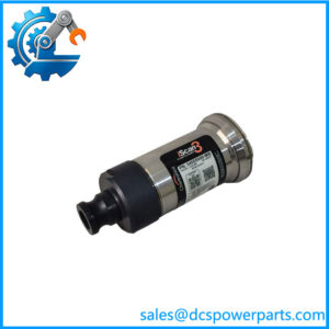
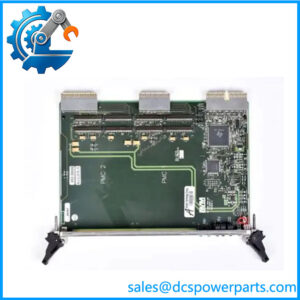
For maintenance teams, the critical issue is identifying which part of the system is being replaced. A request for “UMS2100” could refer to the overall alarm system, a basic alarm panel, an outstation, or a particular internal assembly. A replacement decision should therefore be based on the installed part number, system revision, vessel drawings, I/O channel schedule, and available software backup—not the system name alone.
UMS2100
Application Scenarios & Field Pitfalls — The Engineer’s Perspective
Engineering Pain Point
An alarm-monitoring failure can originate in the sensor wiring, remote I/O, communication network, processing unit, or operator panel. Replacing the visible alarm panel will not resolve a failed field input or an outstation communication fault. Diagnosis should follow the signal path from the initiating contact or transmitter through the acquisition hardware and system processing to the final alarm indication.
Typical Applications
- Main engine and auxiliary machinery alarm monitoring.
- Generator, pump, cooling-water, lubrication, and fuel-system status monitoring.
- Distributed alarm presentation in engine rooms and control rooms.
- Monitoring installations designed for unattended machinery-space operation, subject to the vessel’s approved class and safety arrangements.
Technical Pitfalls to Avoid
- Identify the actual assembly. Confirm whether the requirement is for the complete system, a basic alarm panel, an outstation, or an internal circuit board.
- Preserve the vessel-specific configuration. Back up the alarm list, channel assignments, thresholds, delay settings, alarm groups, and panel configuration before replacement.
- Verify the I/O interface. Confirm signal type, polarity, normal contact state, analog range, and sensor type against the original drawings.
- Check the communications path. Inspect network connections, serial interfaces, addressing, and system-version compatibility before condemning the processing unit or panel.
- Do not copy another vessel’s I/O figures. Channel capacity and the number of binary or analog points vary by project.
- Plan a controlled alarm test. Validate alarm activation, acknowledgment, reset, annunciation, and communication-loss behavior according to the vessel’s approved test procedure.
- Check software and hardware dependencies. Older installations may rely on specific operating-system versions, legacy computer hardware, or system software. Verify recoverability before disturbing a functioning installation.
Related Products and Assemblies
These are associated components or documented system elements, not guaranteed direct replacements.
- UMS-2100 Basic Alarm Panel — 962.005.100/E: Associated with the basic alarm-panel function; confirm the installed panel revision and wiring.
- Basic Alarm Panel (BAP) — 815.001.111: Identified in published project documentation; verify the relevant vessel drawing and outline number.
- System Processing Unit — PCM2200L1-230: A processing-unit model identified in a documented installation; compatibility depends on the software and system revision.
- System Net Board — 810.000.200: Listed as a network board in a documented installation; confirm the original board marking and network architecture.
- Wall-Mounted Outstation — 5151004390: A documented outstation assembly with project-dependent I/O capacity.
- Floor-Mounted Large Outstation — 5151004400: A larger documented outstation assembly; verify the cabinet layout and configured I/O count.
- Dual System Bus Module — SAM401, 800.525.43.0: Listed in marine equipment documentation; confirm system compatibility before substitution.
Procurement Note
Before requesting a replacement, provide the vessel’s system designation, the exact component part number, nameplate photographs, software version, and relevant wiring or system drawings. Confirm whether the requirement is for a complete alarm panel, an outstation, a processor, or an internal board. For legacy installations, availability of compatible hardware alone is insufficient; software recovery, communication compatibility, and documented alarm-function testing should be included in the maintenance plan.