Description
Product Overview
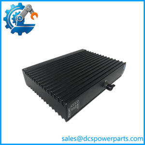
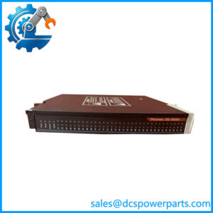
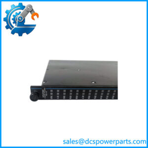
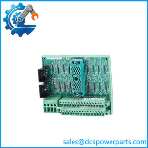
DI3301 is the digital input module of the Trident safety controller — Model 3301, a 32-point discrete input card built on the same triplicated principle as the rest of the platform. It is the module half of a two-part arrangement that is worth separating before anything else: the Model 2301 baseplate (ordering number 7400208B-020 or 7400208C-020) holds the field terminals and supplies the input loading, while this card does the sampling and the diagnosis. The specification itself splits along that line, and the split is the most useful thing an engineer can know about the pair: input impedance is published as more than 30 kΩ without baseplate and about 3 kΩ with baseplate, so the carrier determines what the field circuit sees, and the module determines what the system does with it.
Inside, the card carries three isolated sets of electronics — one channel per main processor. For discrete points, an ASIC on each channel scans every input, compiles the data into an array, and transmits it to the associated MP on demand; the MPs then vote before the result reaches the application. Three channels scanning independently, one ASIC each, is what makes a single failed channel a diagnostic event rather than a wrong reading, and it is why the Fault indicator on this module identifies a channel fault rather than declaring the module dead.
The input characteristics are chosen for plant wiring rather than laboratory signals. Nominal 24 VDC, operational 15 to 30 VDC, 33 VDC absolute maximum, −0.6 VDC reverse tolerance, and thresholds banded at 0 to 5 VDC off, 6 to 14 VDC transition, 15 to 30 VDC on. That wide transition band is the practical part: a switch at the end of a long run, fed by a supply that has sagged, still crosses into the on region before the voltage drop becomes an interlock problem. Input delay is under 10 ms in either direction, with a 6.4 ms time constant and a 3 dB point at 25 Hz — enough filtering to ignore contact bounce on a vibrating skid, fast enough that no trip sequence notices.
The diagnostics are the interesting specification. Triconex states that the module continuously verifies the system’s ability to detect a transition to the opposite state. That targets the failure mode that actually matters in a safety input — a channel that keeps reporting a plausible state while having lost the ability to see a change — rather than merely reporting the state it believes. Combined with the guarantee that the module operates properly in the presence of a single fault, and may continue through multiple faults, this is what allows an input card to be trusted between proof tests.
Each point draws about 8 mA at 24 VDC through the carrier’s loading network, and the module’s field consumption is published per point: 0.2 W at 24 VDC, 0.5 W at 33 VDC. Thirty-two points is therefore roughly 6.4 W and a quarter-amp on the common return — a load to plan into the cabinet’s field supply, not an afterthought. Logic power comes from the MP baseplate at 24 VDC (19.2 to 30 VDC) and stays under 3 W; the only data path is the TMR HDLC I/O bus at 2 Mbit/s. Everything else — terminals, covers, interconnect — belongs to the carrier.
Two carriers are supported: the direct-termination Model 2301, and the DI external termination baseplate with the 9573-610 hazardous-location termination panel where field wiring must be marshalled away from the cabinet. The packaged form is the 5301 Digital Input TriPak, one module plus one 2301 baseplate.
The reseller layer misreads this number badly and consistently. DI3301 appears offered as a “digital I/O module” supporting Ethernet-APL with a supply written as “100–400A1P”, an output frequency of 350 kHz, 2 kg, and a panel protection rating of 31 — a specification set assembled from templates, none of which belongs to a 44 × 220 × 169 mm 24 VDC input card with no output terminals at all. It is also routinely confused with DI3361, which is a different module on a different carrier.
Technical Specifications
| Parameter | Value |
|---|---|
| Model and platform | DI3301 — Triconex Model 3301 Digital Input Module; Trident (Trident v2) TMR safety controller |
| Module type | Digital input; three isolated channels, one ASIC per channel scanning all points; hot-spare capable, mechanically keyed |
| Points | 32, commoned (shared return reference); no per-point isolation |
| Nominal input voltage | 24 VDC |
| Operational voltage range | 15–30 VDC |
| Absolute limits | 33 VDC maximum; −0.6 VDC reverse |
| Input thresholds | 0–5 VDC = off; 6–14 VDC = transition; 15–30 VDC = on |
| Input delay and bandwidth | < 10 ms on-to-off and off-to-on; time constant 6.4 ms; −3 dB at 25 Hz |
| Input impedance | > 30 kΩ without baseplate; approximately 3 kΩ with baseplate |
| Point loading | 0.2 W per point at 24 VDC; 0.5 W per point at 33 VDC |
| Diagnostics | Continuous verification of the ability to detect transitions to the opposite state; fault reported per channel; operation guaranteed through a single fault |
| Isolation and logic power | FE-to-PE 500 VDC min, FE-to-FE (logic) 800 VDC min; logic power 24 VDC (19.2–30 VDC) from the MP baseplate, < 3 W |
| Compatible carriers | Model 2301 Digital Input Baseplate (7400208B-020 / 7400208C-020); DI external termination baseplate with the 9573-610 hazardous-location panel |
| Mechanical and environment | 44 × 220 × 169 mm (W × H × D); 70 °C maximum ambient; I/O bus 2 Mbit/s TMR HDLC |
| Packaging and capacity | 5301 Digital Input TriPak (3301 + 2301); system limit 14 I/O modules, 10 when AO or PI modules are present |
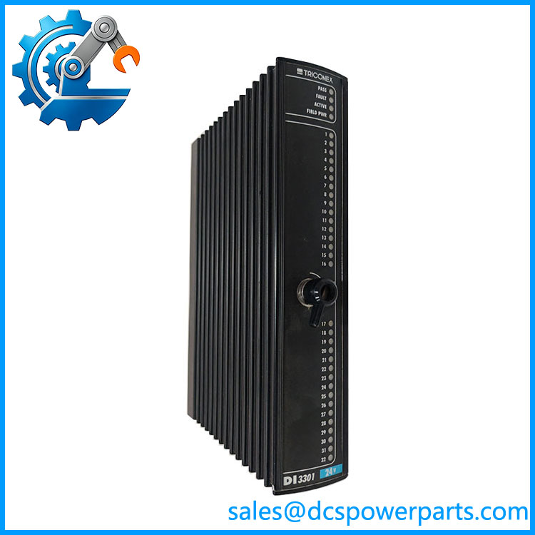
TRICONEX DI3301
Key Features and Advantages
Scanning distributed across three channels: each of the three isolated channel sets has its own ASIC walking all thirty-two points. No channel is a passive listener, so a single failed scanner is detected and voted out instead of quietly degrading the point data.
Diagnostics aimed at the dangerous failure: the module continuously proves it can still detect a transition to the opposite state. A channel stuck at a plausible “closed” is the failure that hides until a trip is needed, and this specification addresses it directly rather than only reporting what the channel currently believes.
Thresholds that survive real cable runs: the 6 to 14 VDC transition band against a 15 VDC on-threshold means four or five volts of drop along a field cable does not turn a closed contact into an unknown. The module reads the circuit the plant actually has, not the one on the drawing.
A 25 Hz input bandwidth that is a feature, not a limit: 6.4 ms time constant and under 10 ms delay suppress contact bounce and drive-induced noise on vibrating equipment, which is exactly where nuisance trips originate. Signals that genuinely pulse faster belong on the pulse input module, and knowing that avoids blaming the card.
Predictable field loading: about 8 mA and 0.2 W per point at 24 VDC, 0.5 W at 33 VDC, published so a cabinet supply can be sized. Thirty-two points at 6.4 W is a number that belongs in the power budget, not in a commissioning surprise.
Commoned points chosen deliberately: one reference for all thirty-two keeps the card compact and matches switches fed from a common isolated 24 VDC. It is the wrong module for floating sources or for circuits needing channel-to-channel isolation, and no configuration changes that.
Service that does not disturb the field: the module is keyed, an I/O set holds an active and a hot-spare card, and every terminal lives on the carrier. A replacement is a lift-and-seat, and the plant’s wiring stays exactly where it was commissioned.
Honest limits: no outputs, no analogue capability, no per-point isolation, and no diagnosis of the field circuit itself — an open switch circuit and an open fuse look alike to the module unless the carrier’s loading makes the difference visible. It is an input card, and its job is to be doubted in the right way.
Applications
Emergency shutdown switch scope: pressure and level switches, valve position limits, and permissives wired into the safety logic, thirty-two points per position, where the wide threshold band and the 10 ms filtering keep long field runs from producing false states.
Burner management panels: flame status, purge and low-fire proving, fuel-valve position feedback — circuits where a contact that chatters with the draft fan must not become a flame-failure trip, and where the module’s bandwidth is doing real work.
Compressor, pump and turbine auxiliaries: lube-oil pressure switches, vibration trip contacts, run-status and overspeed discrete signals, on packages where vibration makes contact bounce a routine condition rather than an exception.
High-integrity pressure protection and tank farm interlocks: discrete inputs from pressure pilots and level switches that must be read deterministically, with the three-channel scan and per-channel fault reporting giving the maintenance team something better than “input bad”.
Legacy Trident columns under spares management: replacing a card in a position already built around 7400208B-020 or 7400208C-020, where the carrier stays and only the module changes — the case where the module number and the baseplate number must not be confused in a purchase order.
Hazardous-area schemes: the same module on the DI external termination baseplate with the 9573-610 panel, where field wiring terminates away from the cabinet and the input card still sees the same electrical behaviour.
Related Products
2301 Digital Input Baseplate Kit (7400208B-020 / 7400208C-020) — the direct-termination carrier that supplies this module’s ~3 kΩ input loading; sold with it as the 5301 TriPak. 5301 Digital Input TriPak — the packaged one-module-plus-one-baseplate combination. DI External Termination Baseplate with 9573-610 DI Hazardous Location Termination Panel — the marshalled, hazardous-area route for the same module. 3361 Analog Input/Digital Input Module — mixed module on carrier 2361, 16 discrete plus 16 analogue points; the route when a position must serve both classes. 7400210-020 Model 2361 AI/DI Baseplate Kit — the mixed carrier, distinguished from the 2301 by its point split. 3401 Digital Output Module with 2401 Digital Output Baseplate Kit — the output counterpart; different terminals, different power path, never interchangeable with input wiring. 3351 Analog Input Module — 32 analogue points on 2351, where continuous measurement rather than discrete state is required. 3381 Pulse Input Module — speed and frequency inputs, the correct destination for signals above the 25 Hz input bandwidth. 2921 I/O Interconnect Assembly and 2281 I/O Bus Extender Module Kit — the passive link inside a column, and the kit that carries the I/O bus beyond eight baseplates or 200 m.
Installation and Maintenance
Before installation: confirm the label reads DI3301 (Model 3301) and not DI3361, and confirm the position carries a Model 2301 carrier, since the module’s input behaviour depends on that carrier’s loading network. Verify the revision marking on the module against the installed base, check keying and lock-lever condition, and establish that the carrier is already terminated so the card can be seated without touching field wiring. Confirm the field supply can carry thirty-two points at 0.2 W each at 24 VDC, and confirm no point needs isolation the commoned design cannot provide.
Installation: seat the module in the slot below the L or R label as the drawing requires, engage the lock lever, and bring the column up. Prove points at the field device — open and close each switch — rather than forcing them in TriStation, and watch the transition timing on a stopwatch-grade test: a point that takes noticeably longer than 10 ms is a field circuit problem, not a card setting. Leave the terminal and slot covers fitted on unused positions, and record the module revision and its carrier’s ordering variant in the as-built file.
Maintenance: a Fault indication is a channel fault, not a failed card — check the field circuit, its supply and its terminations first, and remember the module is specified to keep operating through a single fault. When several points on one card read alike, suspect the shared return or the field supply rather than thirty-two contacts; when one point reads stuck, suspect the contact, the fuse or the terminal. Keep the module as the spare and leave the carrier in place, inspect the carrier terminals on planned outages for corrosion and loosened strands, and verify on each proof test that the module still detects a transition to the opposite state — the diagnostic is continuous, but the record is what an audit asks for.
Warranty and Quality
Every DI3301 is supplied as the Triconex Model 3301 Trident Digital Input Module — 32 commoned 24 VDC points, three isolated scanning channels, thresholds at 0–5 / 6–14 / 15–30 VDC, input delay under 10 ms — and its identity is confirmed by label and revision before dispatch, because this model number circulates online as a “digital I/O module” with Ethernet-APL support, 350 kHz output frequency, 2 kg mass and panel protection ratings that belong to no Triconex product, and because it is regularly confused with the mixed-signal 3361. Each unit is inspected for front-panel and housing condition, connector and lock-lever integrity, keying, indicator operation, and evidence of prior repair, heat damage or moisture ingress. Where a Trident bench is available, the module is seated on a Model 2301 carrier with a switched 24 VDC source, each of a representative set of points is driven through the off, transition and on regions, timing and threshold behaviour are verified, and the module’s transition-detection diagnostic is exercised alongside clean active/hot-spare transfer. A 12-month repair, replacement or refund commitment applies. Technical support covers what this card actually raises: separating the module from the 2301 carrier and from the 3361 mixed module, accounting for the baseplate-supplied ~3 kΩ loading and 8 mA per point, explaining why 25 Hz is the intended bandwidth rather than a shortcoming, and selecting the 9573-610 external panel route where field wiring cannot land at the cabinet.