Description
Product Overview
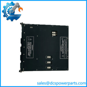
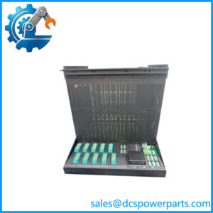
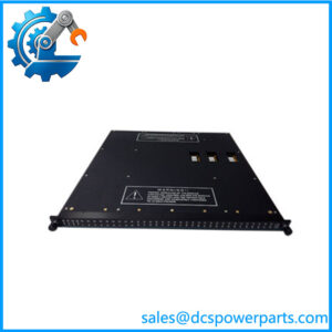
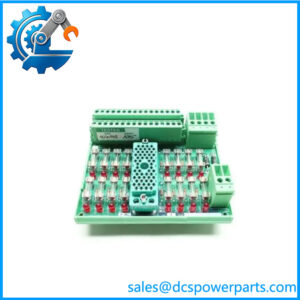
AI2361 7400210-020 is the mixed-signal baseplate of the Trident safety controller: one carrier that terminates sixteen discrete inputs and sixteen analog inputs, for a single Model 3361 Analog Input/Digital Input module seated in one of its two slots. The naming follows the pattern this platform uses everywhere — AI2361 is the Model 2361 designation on the drawings, while 7400210-010 belongs to its sibling, the pure-analog Model 2351, and 7400210-020 is this one. Getting those two ordering numbers the wrong way round is the most common mix-up in the family, and it is resolved by the baseplate’s own assembly number: 3000675-020 here, against 3000675-010 for the 2351.
The reason a mixed baseplate exists at all is density. A plant with eight 4–20 mA transmitters and eight valve-position or interlock contacts on the same skid normally needs two baseplate positions — one analog module, one discrete module, two sets of interconnect joints and two spares. The 3361 collapses that into a single module on a single carrier, with the point map fixed by the platform: points 1 to 16 are digital, points 17 to 32 are analog, and the baseplate’s terminals follow that order. There is no re-mapping — a transmitter wired into the first sixteen terminals is on a discrete channel, and no TriStation configuration changes that. Engineers who know the map wire a cabinet correctly the first time; those who do not spend a commissioning afternoon chasing phantom readings.
The electrical argument is more interesting than the density one. Triconex specifies the analog input impedance as 250 Ω with baseplate and the digital input impedance as roughly 3 kΩ with baseplate, against more than 100 kΩ without it. Both figures say the same thing: the field-side conditioning — the current-sense burden on the analog half, the threshold and loading network on the digital half — is built into the carrier, not the plug-in card. That has three practical consequences. It makes the baseplate a specified electrical component rather than a mounting bracket. It means a AI2361 7400210-020 substituted for a 2351, or vice versa, changes the measurement rather than merely the wiring. And it explains why the digital input power figure is given per point — 0.2 W per point at 24 VDC, 0.5 W at 33 VDC — which is a real load to account for on a wet-contact circuit.
The module’s specifications, taken from the official Product Specifications, are the ones this carrier exists to serve: a 32-point module with three isolated channels, 4–20 mA nominal and 2–22 mA operational on the analog half at 12-bit resolution and 0.15 % of full-scale error with a 16 Hz bandwidth; 15–30 VDC operational with 0–5 / 6–14 / 15–30 VDC off / transition / on thresholds on the digital half; a force-to-value diagnostic on every point; and a scan under 1 ms across all thirty-two points in both cases. The kit ships complete with the interconnect assembly 2921, slot cover 2900 and terminal cover 2901, and the baseplate sits on the standard 178 × 249 mm I/O footprint.
Two variants matter when the cabinet is not ordinary. Model 2342 takes the same module to an external termination baseplate, for wiring brought to a separate marshalling panel; 2342A is its hazardous-location form, used with the 9793-610 termination panel kit. And the packaged route — one 3361 module plus one AI2361 baseplate — is sold as the 5361 Analog Input/Digital Input TriPak, which is what most projects actually order.
The reseller layer here is, as usual, unusable in both directions. One page sells this number as a sixteen-channel differential input module with 0–10 V and 16-bit 100 kS/s sampling and a −40 °C to +85 °C range, none of which appears in any Triconex document. Another sells it as a “safety relay module” with 5 A 250 VAC contacts. A third asserts thermocouple and RTD support, which belongs to the 2352 baseplate with its 9764-510 termination panels, not to this one. Multi-protocol Ethernet, RS-232 and RS-485 support is likewise invented: the module talks to the MPs over the TMR I/O bus, and nothing else.
Technical Specifications
| Parameter | Value |
|---|---|
| Model / ordering number | Triconex AI2361 = Model 2361; ordering number 7400210-020 |
| Manufacturer / platform | Triconex, Invensys; now Schneider Electric — Trident (Trident v2) TMR safety controller |
| Item class | Analog input/digital input baseplate kit — passive carrier |
| Baseplate assembly number | 3000675-020 (I/O baseplate) |
| Kit contents | I/O baseplate; I/O interconnect assembly 2921; slot cover 2900; terminal cover 2901 |
| Point map | 32 points commoned — DI on points 1–16, AI on points 17–32 (fixed by platform) |
| Compatible module | Model 3361 AI/DI module; three isolated channels; 500 VDC FE-to-PE and 800 VDC FE-to-FE (logic) isolation |
| Analog point specification | 4–20 mA nominal, 2–22 mA operational, 33 VDC absolute maximum, 12-bit, 0.15 % of FS (20 mA), 16 Hz bandwidth, FVD diagnostic |
| Digital point specification | 15–30 VDC operational (33 VDC absolute maximum), thresholds 0–5 / 6–14 / 15–30 VDC, input delay < 10 ms, FVD < 2 ms per test |
| Input burdens on baseplate | 250 Ω analog input impedance; approximately 3 kΩ digital input impedance (> 100 kΩ without baseplate) |
| Digital point loading | 0.2 W per point at 24 VDC; 0.5 W per point at 33 VDC |
| Scan performance | < 1 ms for all 32 points; maximum toggle rate to hold diagnostic coverage < 20 per second |
| Field terminals and slots | Compression terminals 24 to 12 AWG (0.2–3.3 mm²); 2 slots (L and R), active / hot-spare, mechanically keyed |
| Dimensions and environment | Baseplate 178 × 249 mm; modules 44 × 220 × 169 mm; 70 °C maximum ambient; logic power 24 VDC (19.2–30 VDC) from MP baseplate |
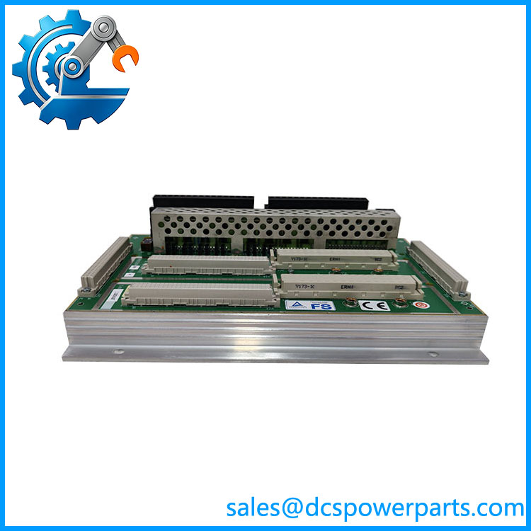
TRICONEX AI2361 7400210-020
Key Features and Advantages
A fixed point map that prevents surprises: points 1–16 are digital and 17–32 are analog, with terminals following that order. The map is not configurable, so a cabinet built to it stays correct through every module swap and every configuration reload — and the drawing is the same as the wiring.
Two burdens, one carrier: 250 Ω on the analog half and about 3 kΩ on the digital half, both quoted with baseplate against more than 100 kΩ without it. The conditioning lives in the carrier, which is why the baseplate model is an electrical decision and why a 2351 substituted into a mixed position changes the measurement rather than just the layout.
Density where panel space is the constraint: sixteen loops of each kind on one carrier and one module, instead of two positions, two interconnect joints and two spare part numbers. On a skid-mounted package or a retrofit into an existing enclosure, that is the difference between fitting and not fitting.
Diagnostics on both halves: the force-to-value diagnostic covers analog and digital points, with the digital test completing in under 2 ms and a documented off-state glitch of under 2 ms at 36 % test voltage. The published consequence is worth reading twice — to keep full diagnostic coverage, input toggle rate above twenty per second is out of scope. Fast-pulsing signals belong on the pulse input module, not here.
Thresholds designed for real field voltages: the 15–30 VDC on-region and the 6–14 VDC transition band tolerate the supply sag and contact resistance found on wet-contact circuits, and the 33 VDC absolute maximum with −0.6 VDC reverse protection covers the usual 24 VDC plant realities.
Commoned points, deliberately: all thirty-two share a reference. That keeps the carrier compact and matches transmitters and contacts fed from a common isolated supply; it is the wrong baseplate for floating sources, thermocouples or per-point isolation, and no configuration changes that.
Wiring that survives module service: every terminal is on the baseplate, modules are keyed, and each I/O set carries an active and a hot-spare module, so a replacement breaks no conductor. Combined with the printed point map, that makes the carrier the stable half of the pair.
Complete kit, protection included: interconnect, slot cover and terminal cover arrive together, restoring the assembly’s protection against dust, liquids and corrosive atmospheres rather than leaving a bare slot in an aggressive plant environment.
Applications
Skid-mounted packages where analog and discrete signals share one enclosure: pressure and flow transmitters alongside valve-position feedback, running contacts and permissives, on a single carrier position. Compressor and turbine auxiliary skids are the classic case — sixteen analog loops and sixteen status contacts in one cabinet, with one module to spare rather than two.
Burner and furnace management panels: analog fuel, air and draft measurements with the discrete permissives, flame-scanner status and limit-switch feedback that surround them. The fixed point map keeps the field wiring schedule unambiguous across a plant’s units, and the wet-contact thresholds absorb the voltage sag typical of long runs from the burner front.
Water and wastewater pumping stations: level and pressure transmitters with float, run-status and interlock contacts in a compact panel, where a mixed carrier avoids adding an enclosure position for a handful of discrete points.
Retrofit of an existing Trident column: where a position must be reused for a mix of signals after a scope change, and where the installed baseplate is the constraint. Confirming whether the position currently carries AI2361 7400210-020 or the pure-analog 2351 decides whether the field schedule can stay as it is.
Packaged equipment with distributed I/O: small Trident configurations that need a modest mix of analog and discrete points rather than full 32-point sets of one type, where the mixed module keeps the point count and the cabinet footprint aligned.
External marshalling arrangements: where field wiring is brought to a separate termination panel, the same Module 3361 moves to the 2342 external termination baseplate, or to 2342A with the 9793-610 hazardous-location panel — the module choice stays, the carrier changes.
Related Products
Model 3361 Analog Input/Digital Input Module — the only module configured for this carrier; 16 DI plus 16 AI, three isolated channels, FVD diagnostics on all points. 5361 Analog Input/Digital Input TriPak — the packaged one-module-plus-one-baseplate combination, the standard ordering route for this pair. 7400210-010 Model 2351 Analog Input Baseplate Kit — the pure-analog sibling sharing assembly family 3000675; the number most often confused with this one. 2342 Analog Input/Digital Input Baseplate Kit, External Termination — same module, field wiring carried to an external marshalling panel. 2342A Analog Input/Digital Input Baseplate Kit, Hazardous Location — the hazardous-area external-termination variant, used with the 9793-610 termination panel kit. 7400208C-020 Model 2301 Digital Input Baseplate Kit — pure-discrete carrier for the Model 3301 module, where a position is all contacts. 2354 / 2354A Analog Input HART Baseplate Kits — analog carriers with HART pass-through; the route when smart transmitters must be read from the asset-management software. 2352 Analog Input Baseplate Kit (TC, RTD, 4–20 mA) — the external-termination analog carrier for thermocouples and RTDs, with 9764-510 panels. 7400209-010 Model 2481 Analog Output Baseplate Kit — the analog output counterpart in the same 7400 ordering block. 2921 I/O Interconnect Assembly and 2281 I/O Bus Extender Module Kit — the passive link inside a column, and the kit that carries the I/O bus to a separate column over 2-ft cable sets.
Installation and Maintenance
Before installation: identify the carrier by its 3000675-020 assembly number rather than by the seller’s description, and confirm it is 7400210-020 and not the pure-analog 7400210-010 sitting one number away. Check the kit for interconnect 2921, slot cover 2900 and terminal cover 2901, confirm a Model 3361 module and matching keying, and establish that logic power reaches the position through the interconnect chain from the MP baseplate. If any point must float, or needs a thermocouple, RTD or HART pass-through, this is the wrong carrier and the requirement belongs to 2354 or 2352.
Installation: mount vertically with airflow clearance and wiring channels along the column, connect the interconnect assembly, and carry the chain onward. Wire to the printed point map — digital on 1–16, analog on 17–32 — and keep it consistent with the loop drawing, because the map cannot be reassigned afterwards. Terminate at 24 to 12 AWG with shields bonded at the cabinet entry, and account for the digital point loading of 0.2 W per point at 24 VDC when sizing the wet-contact supply. Before seating the module, check each analog loop for supply and continuity and each contact for open/closed state at the terminals; a mis-wired point will otherwise present as a channel fault.
Maintenance: inspect compression terminals on planned outages for loosened strands, discolouration and corrosion, and re-torque to specification; on a mixed carrier, a drifting analog reading with a healthy module most often traces to terminal resistance on the analog half, while a stuck discrete point usually traces to the field contact or its wetting supply rather than to the module. Keep the documented toggle-rate limit in view — inputs pulsing faster than twenty per second lose diagnostic coverage, and a “sticky” diagnostic on a fast-cycling contact is a specification mismatch, not a failure. Confirm both interconnect ends are seated, keep terminal and slot covers fitted, and record the assembly number of each baseplate in the as-built file so the next order matches the slot.
Warranty and Quality
Every 7400210-020 is supplied as the Trident Model 2361 Analog Input/Digital Input Baseplate Kit — baseplate 3000675-020 with interconnect 2921, slot cover 2900 and terminal cover 2901 — and is identified by that assembly number before dispatch, because this ordering number is sold online as a sixteen-channel differential input module with 0–10 V ranges and 100 kS/s sampling, as a safety relay module with 5 A contacts, and as a multi-protocol Ethernet gateway, none of which exists in the Triconex documentation. Each unit is inspected for baseplate flatness, connector and terminal-block condition, corrosion, interconnect seating, keying, and completeness of covers, with prior re-termination or field repair noted. Where a Trident bench is available, the carrier is populated with a Model 3361 module pair, powered through the column interconnect, exercised on analog points across 4, 12 and 20 mA and on digital points through the 0–5 / 15–30 VDC threshold regions, and checked for clean active/hot-spare transfer and correct force-to-value diagnostic response on both halves. A 12-month repair, replacement or refund commitment applies. Technical support covers what this carrier raises in practice: separating 7400210-020 from 7400210-010, wiring to the fixed point map, accounting for the baseplate-supplied input burdens, and choosing between 2361, 2342 and 2342A for a given marshalling arrangement.