Description
Product Overview
469-P5-HI-A20-E is a Multilin 469 motor management relay in the SR-series draw-out construction, and the order code is the whole specification. Read it left to right and there is no ambiguity left: 469 is the platform, P5 says the phase CT secondaries are 5 A, HI says the control power input accepts 90–300 VDC or 70–265 VAC at 48–62 Hz, A20 says the four analog outputs are 4–20 mA rather than 0–1 mA, and E says the front panel is the enhanced version with the larger LCD. Nothing in that string says Ethernet.
The last letter is where most of the confusion in the market sits. In GE’s order code, E is the enhanced display; the network options are separate positions — T for the enhanced display with 10Base-T Ethernet, D for the enhanced display with DeviceNet — and H is a trailing suffix for harsh-environment conformal coating. A relay bought as -E therefore communicates over its front RS-232 programming port and its rear RS-485 ports using Modbus RTU, and a project that assumed Modbus TCP will discover the mistake at commissioning, not at the quotation stage. Distributor pages that decode “E” as Ethernet are reading a different product family’s convention into this one.
What the relay does is the reason the code is worth learning. The 469 protects a medium or large horsepower motor with a thermal model rather than a current-only overload: the model is biased by measured stator RTD temperature and by negative-sequence current, so a motor whose cooling is partially blocked trips before its insulation fails, and a healthy motor running close to its limit does not nuisance-trip. It adds mechanical jam, stall and acceleration protection, starts-per-hour and time-between-starts control, current unbalance, ground fault down to fractions of an amp with the sensitive core-balance CT, undercurrent, voltage and frequency elements, and a full metering set on top — current, voltage, power, energy, power factor, thermal capacity used, starts.
The construction is the second half of the product. The relay is a draw-out unit in a fixed case: the case keeps the field wiring, and shorting bars in the case short the CT secondaries as the unit is withdrawn, so no trip or alarm is produced and no CT circuit is left open. On a running plant that turns a relay replacement from a planned outage with a CT re-termination into a swap that a competent electrician can do in minutes.
The honest caveat belongs in the overview rather than the small print: GE has moved this platform forward — the Multilin 869/859 is the recommended successor and GE’s own store runs a 469-to-869 upgrade path — so 469-P5-HI-A20-E is sustained by tested stock rather than by current manufacture. For a plant with a dozen of these on critical drives, that makes a verified spare a maintenance decision, not a procurement detail.
Technical Specifications
| Parameter | Value |
|---|---|
| Model / order code | 469-P5-HI-A20-E in SR469 case; P5 = 5 A phase CT, HI = high-range control power, A20 = 4–20 mA analog outputs, E = enhanced display |
| Manufacturer / series | GE Multilin (GE Vernova Grid Solutions), Multilin 469 / SR469 |
| Product type | Motor management relay, microprocessor-based, draw-out unit in fixed case |
| Control power (HI) | 90–300 VDC; 70–265 VAC at 48–62 Hz (LO variant: 20–60 VDC / 20–48 VAC) |
| Power consumption | 25 VA typical, 45 VA maximum |
| Phase current inputs | CT secondary 5 A (P5); conversion range 0.05–20 × CT; burden < 0.2 VA at rated load; nominal frequency 20–70 Hz |
| Ground current inputs | 1 A / 5 A CT input plus a dedicated 50:0.025 core-balance CT input for sensitive earth-leakage detection |
| RTD inputs | 12 inputs, 3-wire, field-programmable type: 100 Ω platinum, 100/120 Ω nickel, 10 Ω copper |
| Analog outputs (A20) | Four isolated channels, 4–20 mA; ±1 % of full scale; maximum load 1200 Ω; isolation 36 Vpk |
| Output relays | Six Form-C relays, silver-alloy contacts, 10 ms operate time; five non-failsafe plus one failsafe SERVICE relay |
| Communications (this build) | Front RS-232 programming port; rear RS-485 (Modbus RTU); no Ethernet and no DeviceNet with the E suffix |
| Construction / environment | Draw-out unit with automatic CT shorting bars; relay powered from station battery or AC control supply; operating range as published for the 469 platform |
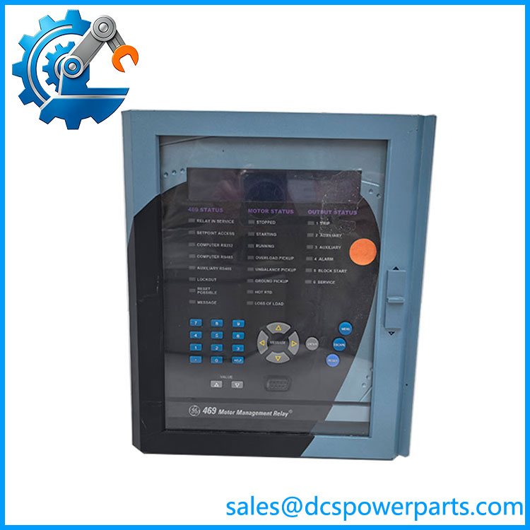
SR469 469-P5-HI-A20-E
Key Features and Advantages
Order code you can defend: 469-P5-HI-A20-E states its CT rating, its control-power window, its analog output range and its display class in four characters. On a spare-parts shelf where several 469 variants sit side by side, that is the difference between picking the right unit first time and discovering a 1 A CT unit in a 5 A panel.
HI control power across the plant’s whole range: 90–300 VDC and 70–265 VAC in one part number covers a 125 V station battery, a 220 V battery, and a 230 V AC control bus without a variant for each. On a site with mixed switchgear vintage, one spare serves the lot — a genuinely practical advantage that the LO variant does not offer.
Thermal model biased by real temperature: the 469 does not guess winding temperature from current alone. Stator RTD feedback and negative-sequence biasing correct the model, which is how it catches a blocked cooler, a fouled fan or a supply imbalance that a current-only relay reads as normal load. Fifteen standard overload curves plus custom and voltage-dependent forms let the relay follow the motor manufacturer’s published thermal limit instead of a conservative approximation.
Starting protection that separates “hard start” from “wrong start”: stall and acceleration elements, starts-per-hour and time-between-starts limits, restart block after a trip, and a second overload curve for two-speed motors. For a crusher, a ball mill or a high-inertia fan, the value is not the trip — it is the trip that happens before the rotor is damaged and the one that does not happen when the start was merely slow.
Ground fault sensitivity that reaches personnel-protection levels: with the 50:0.025 core-balance CT the relay resolves earth leakage in the fractions-of-an-amp region, which is what mining and wet-process installations need and what a 5 A ground CT input cannot deliver.
Six output relays with a failsafe one among them: five are non-failsafe and energize to operate; the sixth, the SERVICE relay, is failsafe and drops out when the relay loses control power. That asymmetry is deliberate — it gives the scheme a watchdog contact that opens on loss of the relay itself, without turning every trip contact into a fail-safe liability.
Four 4–20 mA outputs that will drive a real loop: 1200 Ω maximum load at ±1 % of full scale is enough for a long run to a DCS input card, so current, thermal capacity used, hottest RTD and motor load can be mirrored into the plant system without external transducers.
Draw-out with automatic CT shorting: the case shorts the CT secondaries as the unit is withdrawn and keeps every field conductor in place, so a suspect relay can be exchanged without opening a CT circuit and without a trip. For a plant that tests relays on a rolling basis, this is the feature that makes the maintenance schedule achievable.
Diagnostics that answer the question after the trip: time-stamped event records, pre-trip data and trending let the investigation start from the relay’s own record of what happened rather than from an operator’s recollection, which is how a repeat tripper gets fixed instead of reset.
Applications
Boiler feed pumps and cooling-water pumps in power stations: continuous duty, high consequence of loss, and often the motor whose failure forces a unit derate. The 469-P5-HI-A20-E earns its place here because the thermal model sees a rising stator temperature weeks before the insulation gives way, and the analog outputs put thermal capacity used on the plant DCS where an operator will actually look at it.
Induced and forced draft fans: high-inertia starts where acceleration time can exceed the safe stall time on a low-voltage start. Voltage-dependent overload curves and stall protection are what keep a legitimate slow start from becoming a trip, and a genuinely stalled rotor from becoming a rewind.
Refinery and petrochemical pump and compressor drivers: motors in corrosive, humid, sometimes classified surroundings, protected against jam, unbalance and earth leakage, with event records that satisfy an investigation after an unplanned shutdown.
Cement and mining duty: crushers, mills and conveyors where jam protection and repeated-start control matter more than metering accuracy, and where the sensitive ground CT input covers earth-leakage protection that a standard ground CT cannot resolve.
Water and wastewater: large pumps and blowers on wet, humid sites where a relay that survives the atmosphere and reads bearing RTDs is worth more than one with more features, and where the draw-out case keeps the CT wiring untouched through a swap.
Retrofit of electromechanical overload protection: panels where a thermal overload relay, an RTD scanner, a transducer and a meter are being replaced by one device — the commonest reason a -E unit is bought today, usually without a network requirement, which is exactly why the missing Ethernet option does not matter in that application but does matter if someone assumed it.
Related Products
469-P5-HI-A20-T — the same relay with the enhanced display and 10Base-T Ethernet; the variant to order when Modbus TCP or DNP over Ethernet is actually required. 469-P5-HI-A20-D — enhanced display with DeviceNet, for plants whose network standard is DeviceNet rather than Ethernet or serial. 469-P5-HI-A20-E-H — identical to this unit plus the harsh-environment conformal coating, the usual choice for hydrogen sulphide, salt air or high-humidity cabinets. 469-P1-HI- — 1 A phase CT version of the same build; not interchangeable with a 5 A CT installation, and the commonest cause of a wrong spare. 469-P5-LO- — low-range control power variant (20–60 VDC / 20–48 VAC); an LO unit must never be connected to a 220 V control bus. SR469 case — the fixed draw-out case that holds the field wiring and the CT shorting bars; a replacement unit needs the case type to match, including the collar used in shallow switchgear. 369-HI-R-M-0-0-0 — the smaller Motor Management Relay for medium and low-voltage motors, where the 469’s feature set is more than the application needs. 489-P5-HI- — the generator protection sister in the same SR draw-out family; same order-code grammar, different protection philosophy and different ANSI element set. 869 / 859 — the Multilin 8 Series successors GE recommends for a 469 end-of-life migration, with retrofit kits that reuse the existing panel cutout. HGF3 / HGF5 / HGF8 and 50:0.025 CT — sensitive ground-fault accessories used with the 469’s dedicated core-balance input for low-level earth-leakage protection.
Installation and Maintenance
Before installation: read the unit label and confirm it says 469-P5-HI- — phase current inputs 5 A, control power HI, analog outputs 4–20 mA, enhanced display. Confirm the associated CTs really are 5 A secondary; a 1 A CT installation needs the P1 variant, and the mismatch produces readings that are wrong by a factor of five rather than obviously broken. Verify the control supply is inside 90–300 VDC or 70–265 VAC before closing the control breaker, check the case is the SR type with the correct collar depth for the switchgear, and confirm the ground CT tap in use — only one ground CT input tap should be wired on a given unit. Do not open a CT secondary circuit at any point in the work; the CTs must be shorted before any conductor is disturbed, and in the SR case the shorting bars do that for you only if the unit is withdrawn through the intended procedure.
Commissioning: with the unit in its case and control power applied, verify the display and status LEDs, then confirm the motor nameplate data, CT primary and VT configuration in the settings before any protection is enabled. Set RTD types to match the sensors actually installed — 100 Ω platinum, 100/120 Ω nickel and 10 Ω copper behave very differently, and a wrong type produces plausible but wrong temperatures. Enable the elements in a defined order, test each output relay into a dummy load, and confirm the 4–20 mA outputs against a milliammeter at both ends of their range. If the plant expects Modbus TCP, stop here: this build has no Ethernet port, and the integration has to go through RS-485 or be re-specified as a -T.
Maintenance: exercise the draw-out mechanism at planned outages rather than for the first time under pressure, and inspect the case’s shorting bars and terminal condition while the unit is out. Check CT and VT wiring for tightness and corrosion, verify RTD lead resistance where readings look noisy, and compare the relay’s own metering against a clamp-on reference — a drifting channel is easier to find before it is trusted. Back up the settings file from every unit; a spare 469-P5-HI- is only a spare if the configuration can be restored into it, and the settings file is also the record that tells the next engineer which variant is installed.
Warranty and Quality
Every 469-P5-HI- is supplied as the relay its order code describes — 5 A phase CT inputs, HI control power, four 4–20 mA analog outputs, enhanced display, no Ethernet — and never as the “Ethernet model” that careless listings imply. Each unit is identified by nameplate before dispatch so the buyer sees the exact code that will arrive, and the build is confirmed against the panel it is going into: CT secondary rating, control-power range, case type and collar depth. Units are visually inspected for case and terminal condition, display integrity, evidence of prior repair and label consistency, and where a protection test set is available they are powered and checked through the front panel, exercised with injected current and RTD simulation on representative channels, and verified for correct output relay operation and analog output scaling. A 12-month repair, replacement or refund commitment applies. Technical support covers the questions this part actually generates: why -E is a display option and not Ethernet, which suffix adds the network, how P5 and P1 differ in the field, how the draw-out case protects the CT circuits, and what a 469-to-869 migration means for a plant that still has a decade of service left in the switchgear.