Description
Rockwell Automation ICS Triplex T8311
Product Overview
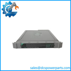
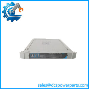
The Rockwell Automation ICS Triplex T8311 is a Trusted TMR Expander Interface used to extend the Trusted safety-system architecture beyond the primary controller chassis. Its job is architectural rather than application-level I/O: the module provides the master interface between the Trusted Controller Chassis Inter-Module Bus (IMB) and the Expander Bus, allowing additional Trusted chassis to communicate with the controller while preserving the system’s fault-tolerant architecture. Rockwell identifies the T8311 as part of the Trusted Expander module family and lists it as the product description Trusted TMR Expander Interface.
Internally, the T8311 uses a TMR/HIFT architecture with three fault-containment regions. Messages exchanged through the architecture are re-synchronized and majority-voted, with diagnostics available for communication errors, watchdog status, active/standby state, and module health. The current Rockwell documentation specifies a 250 Mbps Expander Bus, 20–32 VDC backplane supply range, and up to 30 m using the TC-301 copper connection or 10 km when T8314 fiber transmitter/receiver units are used.
For maintenance engineers, one detail is particularly important: T8311 belongs to the Trusted expansion architecture, so it should not be evaluated as a generic Ethernet communication card. Its compatibility depends on the Trusted chassis, T8310/T8311 expansion architecture, T8312 adapter arrangement, approved cable assemblies, and system configuration. Rockwell documentation also supports active/standby configurations and module replacement procedures, making the relevant to maintenance of installed Trusted safety systems.
Product Introduction
Expanding a Trusted safety controller is not simply a matter of adding another communications card. The provides the dedicated bridge between the controller’s triplicated IMB and the Trusted Expander Bus, with hardware-level fault containment built into the interface.
For a Trusted TMR system expansion or legacy replacement, the critical matching points are the module designation, chassis position, T8312 interface adapter, T8310/T8310C expander processor, and approved communication cable arrangement.
Key Technical Specifications
| Parameter | Specification |
|---|---|
| Product Model | |
| Manufacturer | Rockwell Automation / ICS Triplex |
| Product Family | Trusted |
| Product Type | Trusted TMR Expander Interface |
| Architecture | TMR / HIFT |
| Backplane Supply | 20–32 VDC |
| Maximum Load | 40 W |
| Heat Dissipation | 40 W |
| Compatible Chassis | T8300 Trusted Expander Chassis |
| Module Clock | 50 MHz |
| Expander Bus Data Rate | 250 Mbps |
| I/O Interface | Expander Chassis backplane |
| Copper Communication Distance | 30 m using TC-301 |
| Fiber Communication Distance | 10 km using T8314 Fiber TX/RX Units |
| Operating Temperature | -5°C to +60°C |
| Non-operating Temperature | -25°C to +70°C |
| Operating Humidity | 5–95% RH |
| Dimensions | 266 × 31 × 303 mm |
| Weight | 1.14 kg |
| Safety Certification | Designed for TÜV / IEC 61508 SIL 3 applications |
The specifications above follow Rockwell’s later PD- Issue 12/15 documentation. Older documentation contains different physical dimensions and weight figures, so revision identification is important when comparing legacy manuals or physical hardware.
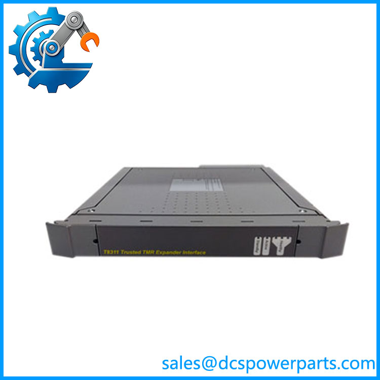
T8311
Major Features / Practical Advantages
TMR Fault-Tolerant Architecture
The is built around Triple Modular Redundancy rather than a conventional single-path communications design. The module contains three fault-containment regions, with isolation between the regions to limit fault propagation. Rockwell describes the architecture as HIFT and specifies fault-tolerant 3-2-0 operation.
This matters when the module is used as part of a safety-system expansion. A failed communication path does not simply become an ordinary network outage; the Trusted architecture monitors channel health and maintains the appropriate redundant operating state.
Controller-to-Expander Interface
The connects the controller-side IMB with the Expander Bus. Rockwell documentation specifies that the triplicated IMB operates at up to 12.5 Mbps, while the Expander Bus provides the high-speed interconnection to the expansion architecture.
The interface therefore belongs to the Trusted backplane architecture. It should not be configured as though it were a standard Modbus TCP, PROFIBUS, or general-purpose Ethernet communications module.
250 Mbps Expander Bus
The current product documentation specifies a 250 Mbps Expander Bus data rate. The supported physical architecture provides up to 30 m using the TC-301 copper connection. For longer distances, Rockwell specifies the use of T8314 fiber TX/RX units, with a documented maximum of 10 km.
Active / Standby Operation
Trusted systems can use paired modules in a hot-standby configuration. Rockwell states that when both modules are installed, the TMR Processor determines which module is active according to module condition. In a fault condition, the system can switch to the healthier module, reducing the need for an immediate process interruption.
This is an important distinction from simply having two installed communication cards: the active/standby relationship is part of the Trusted system configuration.
Hot Replacement
The documentation explicitly supports hot replacement and describes replacement of an active or standby module within the appropriate Trusted maintenance procedure.
That does not mean the module should be pulled casually. The system must be in the correct configuration, the healthy partner must be confirmed where required, and the manufacturer’s maintenance procedure must be followed.
Diagnostic Information
The module records and reports information including Expander Bus link quality, receive-error counts, frame/checksum discrepancies, HIFT clock status, watchdog condition, active/standby status, IMB status, module type, and serial number.
For troubleshooting, this is considerably more useful than simply checking whether a communications LED is illuminated.
Related Products
- T8310 — Trusted TMR Expander Processor that works with the expansion architecture connected through the .
- T8310C — Conformal-coated version of the Trusted TMR Expander Processor family.
- T8311C — Conformal-coated version of the family; the “C” designation should not be assumed interchangeable without checking environmental and system requirements.
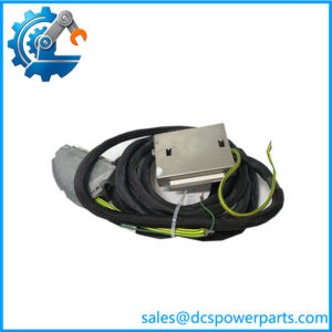
- T8312 — Trusted Expander Interface Adaptor Unit used between the and associated expander communication hardware.
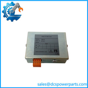
- T8314 — Trusted Fiber TX/RX Unit for long-distance optical Expander Bus connections.
- T8300 — Trusted Expander Chassis associated with the /T8310 expansion architecture.
- TC-301 — Expander Interface Hot Link Cable used for the -to-T8310 copper connection.
- TC-302 — Cable arrangement used with the T8312 and fiber TX/RX architecture.
- T8100 — Trusted Controller Chassis in which the is installed in an I/O module slot.
Rockwell’s current Trusted documentation explicitly identifies T8310/T8310C//T8311C as Trusted Expander Modules and separately identifies T8312 and T8314 as associated expansion-interface hardware.
FAQ
What is the Rockwell ?
The is a Trusted TMR Expander Interface Module. It provides the interface between the Trusted Controller Chassis IMB and the Expander Bus, allowing the Trusted architecture to extend to additional chassis.
Is a digital I/O module?
No. It is a communications/interface module for the Trusted expansion architecture, not a conventional digital-input or digital-output module.
What chassis does work with?
Rockwell’s specification identifies the T8300 Trusted Expander Chassis as the associated chassis, while the itself is installed in an I/O slot of the Trusted Controller Chassis.
Can I hot-swap the ?
Yes, the Trusted documentation supports hot replacement, including replacement in hot-standby configurations. The procedure is configuration-dependent, however. Confirm the partner module is healthy and follow the Rockwell Trusted maintenance procedure rather than treating it as ordinary powered communications hardware.
What is the Expander Bus speed?
The current Rockwell specification gives an Expander Bus data rate of 250 Mbps. Older documentation contains a historical 1.5 Gbps figure, which is why revision control matters when reconciling old system documentation. For procurement and current system engineering, use the specification applicable to the installed Trusted release and hardware revision.
What is the maximum cable distance?
With the specified TC-301 copper cable, the documented maximum is 30 m. Using T8314 fiber TX/RX units, the documented maximum is 10 km.
Does use Modbus TCP or PROFIBUS?
Do not identify it as a Modbus TCP or PROFIBUS interface. The communicates through the proprietary Trusted IMB and Expander Bus architecture. Rockwell’s documentation specifies the Expander Bus and associated Trusted hardware rather than those general-purpose fieldbus protocols.
Does support SIL 3?
The Trusted documentation states that the is designed for TÜV certification to IEC 61508 SIL 3 in safety-critical applications. The module’s certification status should still be evaluated as part of the complete safety-system architecture and applicable configuration, not as an independent SIL rating for an arbitrary application.
What should I verify before purchasing a replacement ?
Verify the complete designation, hardware/revision marking, Trusted system release, controller chassis, /T8310C expander processor, T8312 adapter, cable type, and whether the installation uses a single or hot-standby pair. Also confirm whether a T8311C conformal-coated variant is actually required. Rockwell distinguishes the “C” modules as conformal-coated versions.
Procurement Note
The is safety-system infrastructure, so part-number matching alone is not enough. Confirm the installed Trusted architecture and the associated ///cable configuration before approving a replacement.
One procurement trap is especially worth flagging: older documentation reports different physical dimensions and weight from later Rockwell documentation. That does not automatically mean the documents describe different electrical products, but it is a strong reason to record the hardware revision and Trusted release when matching an installed unit.
For New Surplus stock, inspect the front-panel LEDs, rear connectors, module identification label, ejector hardware, storage condition, and revision markings. A visually clean Trusted module is not proof that its communication channels or redundancy functions have been tested. For a safety-system spare, request traceable identification and functional test evidence whenever available.