Description
Key Technical Specifications
| Parameter | Specification |
|---|---|
| Model | G122-829A-001 |
| Manufacturer | MOOG |
| Control function | P, I, or P+I selectable |
| Input channels | 1 single-ended and 2 differential inputs |
| Input signal options | 4–20 mA or ±10 V, depending on input and switch configuration |
| Feedback input | Differential 4–20 mA or ±10 V |
| Transducer excitation | +10 VDC, 10 mA maximum |
| Output options | ±10 V, selectable current output, or 4–20 mA |
| Maximum current output | ±100 mA |
| Enable input | +24 VDC, 17–32 V |
| Dither | 200 Hz, selectable on/off |
| Supply voltage | 24 VDC nominal, 22–28 V |
| Supply current | 200 mA maximum |
| Mounting | DIN rail |
| Protection rating | IP20 |
| Operating temperature | 0°C to +40°C |
| Dimensions | 100 × 108 × 45 mm (W × H × D) |
| Weight | 180 g |
Specifications are taken from MOOG’s G122-829A technical datasheet. Output configuration and input scaling depend on internal switch settings and plug-in resistor arrangements.
Product Introduction
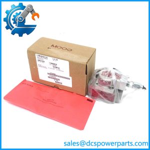
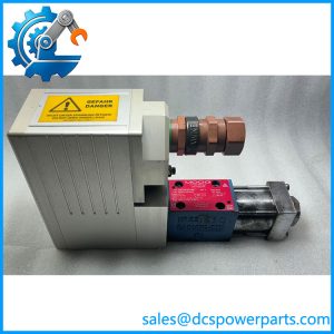
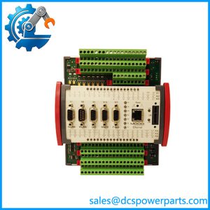
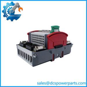
The MOOG G122-829A-001 is an analog servo amplifier intended for closed-loop control systems requiring proportional action, integral action, or a combination of both. It accepts command and feedback signals, combines them into an error signal, and processes that error through configurable P-I control stages. The resulting output can be configured as voltage, current, or 4–20 mA to operate a compatible servo valve or proportional valve.
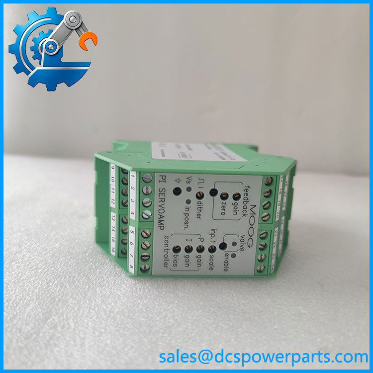
G122-829A-001
The amplifier includes front-panel adjustment potentiometers, status indicators, test points, an enable input, and a step function for tuning. Its internal switches allow engineers to configure signal ranges, feedback characteristics, output type, integrator behavior, and dither. These settings make it important to preserve the original configuration when replacing a working unit. MOOG’s newer IN122-829A001 is the documented replacement designation, but the replacement should still be checked against the installed wiring and application settings.
Application Scenarios & Field Pitfalls
Typical applications
- Electrohydraulic servo valve control.
- Closed-loop hydraulic actuator positioning.
- Industrial machinery requiring proportional and integral regulation.
- Hydraulic pressure, flow, or position-control loops where the installed system uses compatible transducers and valve interfaces.
- Retrofit and maintenance of legacy MOOG analog control systems.
Important field pitfalls
- Output configuration: The amplifier supports voltage, selectable current, and 4–20 mA outputs. Confirm the installed valve’s electrical requirements before connecting a replacement. Incorrect output selection can damage the valve interface or prevent proper operation.
- Feedback polarity: The command and feedback signals must produce negative feedback in the control loop. Incorrect polarity can cause unstable or unintended actuator movement. MOOG specifically addresses feedback polarity in its application notes.
- Internal configuration: Switch positions and plug-in resistors affect gain, signal scaling, current output, and dither. Do not assume a replacement has the same settings as the removed unit.
- Installation environment: Keep the top and bottom ventilation openings clear. MOOG also recommends attention to screened signal wiring and electromagnetic interference from nearby drives.
Related Products
| Model | Description | Relationship |
|---|---|---|
| IN122-829A001 | P-I servo amplifier with in-position signal | MOOG-documented replacement |
| G122-829A011 | P-I servo amplifier with cable-break detection | Related model variant |
| IN122-829A011 | P-I amplifier with cable-break detection | Newer related variant |
The IN122-829A001 is the direct replacement identified in MOOG’s ordering information. The A011 variants have a different cable-break detection configuration and should not be treated as direct substitutes without application review.
Procurement and Quality-Control Notes
Before purchasing a G122-829A-001, verify:
- Exact model marking: G122-829A001.
- Terminal condition and terminal numbering.
- Internal switch positions and plug-in resistor configuration.
- Condition of front-panel potentiometers and indicators.
- Stable 24 VDC operation within the specified 22–28 V range.
- Correct response to command and feedback signals.
- Output configuration under the intended valve load.
- Enable, in-position, and dither functions.
Lifecycle and replacement note: MOOG’s documentation identifies IN122-829A001 as the newer replacement for G122-829A001. A secondary product record also describes the older G122 model as discontinued, but the OEM replacement documentation is the stronger reference for procurement planning.
Procurement recommendation: For an existing machine, prioritize an exact G122-829A001 match when maintaining the original configuration. If considering IN122-829A001, verify terminal assignments, control-loop settings, and commissioning requirements before installation.