Description
Technical Specifications
| Parameter | Specification |
|---|---|
| Product Model | MTL838C |
| Manufacturer | Eaton MTL |
| Product Type | Analog multiplexer receiver |
| System Family | MTL830C |
| Compatible Transmitter | MTL831C |
| Maximum Transmitters | 2 |
| Maximum Sensor Inputs | 32 |
| Communication Protocol | Modbus RTU |
| Serial Interfaces | 2 × RS-485 |
| Serial Baud Rate | 300–19,200 baud |
| Data Format | 8 data bits, 1 stop bit; odd, even, or no parity |
| Configuration Interface | USB |
| Alarm Outputs | 2 programmable relay contact pairs |
| Supply Voltage | 19–30 VDC |
| Maximum Current | 300 mA |
| Operating Temperature | -40°C to +70°C |
| Storage Temperature | -40°C to +85°C |
| Typical Response Time | 500 ms |
| Maximum Modbus Network Size | Up to 31 MTL838C receivers per Modbus master network |
| Weight | Approximately 0.19 kg |
| Installation Location | Safe area or approved Zone 2 installation, depending on certification and conditions |
Specifications are based on Eaton’s MTL830C receiver documentation. The standard MTL838C is the Modbus RTU/RS-485 version; Ethernet-based Modbus TCP is associated with the MTL838C-MBT variant.
Product Introduction
Eaton MTL838C Temperature Multiplexer Receiver
The Eaton MTL838C receives multiplexed measurements from MTL831C field transmitters and makes up to 32 sensor values available to the host control system. It supports thermocouple, RTD, millivolt, and potentiometer measurement applications through the associated transmitter hardware.
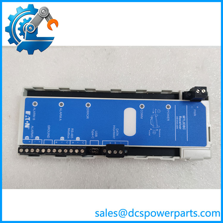
MTL838C
Dual RS-485 interfaces provide Modbus RTU connectivity, while the USB port supports system configuration and diagnostics. Two programmable alarm relays provide additional status signaling for plant alarm circuits. The receiver retains its configuration in onboard memory during power loss.
Application Scenarios & Field Pitfalls
The is used where multiple temperature and analog measurement points must be collected from hazardous process areas without installing an individual signal cable for every sensor. It centralizes the data received from field transmitters and presents it to the control system through a serial communication interface. Communication faults, incorrect register mapping, and transmitter configuration mismatches are common causes of commissioning problems.
Typical applications
- Petrochemical plants: Collects distributed thermocouple and RTD measurements from process equipment.
- Oil and gas facilities: Transfers hazardous-area sensor measurements to control-room PLC or DCS systems.
- Chemical processing: Consolidates temperature measurements from reactors, vessels, and pipelines.
- Industrial monitoring systems: Provides Modbus-based access to multiple field measurement points through a shared data highway.
Engineering checks before installation
- Verify the transmitter configuration. The supports up to two MTL831C transmitters. Confirm the number of transmitters, sensor assignments, and channel configuration before commissioning.
- Check the communication variant. uses RS-485 interfaces; -MBT is the Modbus TCP/Ethernet version. These are not interchangeable without checking the host interface and system design.
- Confirm the communication protocol. The receiver supports Modbus RTU and, in applicable configurations, Honeywell LLMUX. The required protocol must be selected and configured using the MTL83xC software.
- Verify Modbus parameters. Check slave address, baud rate, parity, register format, and master-side polling configuration. A mismatch can produce communication errors or incorrectly interpreted measurements.
- Inspect the data highway. Check the shielded twisted-pair cable, polarity, grounding, isolator, and transmitter power arrangement. For Zone 0 or Zone 1 transmitter installations, use the specified MTL5553 isolator/power supply or an approved equivalent configuration.
- Test alarm relay behavior. The two programmable relay contacts open when their configured alarm conditions occur. Confirm the relay logic and receiving circuit before placing the system into service.
These checks are consistent with Eaton’s receiver manual and MTL830C configuration documentation.
Related Products
| Model | Function Difference | Potential Application |
|---|---|---|
| MTL831C | 16-channel analog transmitter for thermocouple, RTD, mV, and potentiometer inputs | Field-side sensor acquisition |
| MTL831C-PS | MTL831C version with pluggable screw-terminal inputs | Installations requiring removable sensor terminals |
| -MBT | Receiver with Modbus TCP/Ethernet connectivity | Ethernet-based PLC and DCS integration |
| -EIP | Receiver variant with EtherNet/IP connectivity | EtherNet/IP control-system integration |
| MTL5553 | Intrinsic-safety isolator and power supply for the data highway | Hazardous-area transmitter installation |
| FCS-9616 | Junction box for 16 sensor connections and one transmitter | Field sensor termination |
| FCS-9632 | Junction box for 32 sensor connections and two transmitters | Higher-density field measurement installations |
These products serve different roles within or alongside the MTL830C system. The -MBT and -EIP should be selected according to the actual host communication protocol, not simply because they share the same receiver family.
Procurement and replacement note: Before ordering an , confirm the complete model designation, communication protocol, hardware revision, and existing transmitter arrangement. Do not replace an MTL838B receiver with an as a unit-only substitution. Eaton’s discontinued-product guidance states that migration from the MTL830B generation to MTL830C requires replacement of the complete transmitter, isolator, and receiver system because the generations use different physical-layer technology.