Description
Product Overview
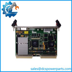
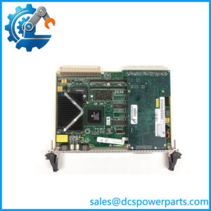
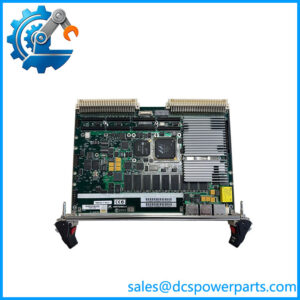
The Motorola MVME162-513A is a 6U VMEbus embedded controller designed for industrial computing, real-time control, and equipment integration. It belongs to the MVME162 family and uses a Motorola MC68040 processor running at 32 MHz, including an integrated floating-point unit. The documented -513A configuration includes 4 MB of DRAM, 512 KB of battery-backed SRAM, and 1 MB of Flash memory. These resources support embedded operating systems, control applications, diagnostic software, and machine-level data processing. The board combines processor, memory, communication, and bus-interface functions on a single VMEbus card.
The MVME162 architecture provides several interfaces for integration into larger systems. Its VMEchip2 supports communication between the local processor bus and the VMEbus backplane, including system-controller and DMA functions. The documented -513A configuration also includes an Ethernet transceiver interface, an SCSI interface with 32-bit local-bus burst DMA, two serial communication ports, and four IndustryPack interfaces. External I/O is routed through the P2 connector and compatible transition hardware. This architecture makes the Motorola MVME162-513A suitable for legacy industrial controllers, test systems, data acquisition equipment, and other installations built around the VMEbus standard.
Replacement planning requires attention to the complete board configuration rather than the MVME162 family name alone. Processor type, memory capacity, SCSI and Ethernet options, serial-port configuration, VMEbus interface, firmware image, and board artwork revision can affect system operation. The Motorola MVME162-513A should be checked against the installed board identifier and system software before procurement. A board with a similar front-panel appearance may not contain the same optional interfaces or memory configuration.
Product Introduction
When a legacy VME-based control system stops booting, replacing the CPU board is only part of the recovery process. The replacement must preserve the installed processor architecture, memory configuration, peripheral interfaces, and boot environment. Differences in SCSI configuration, Ethernet hardware, or serial-port modules can prevent an otherwise functional board from operating correctly in the existing system.
The -513A is a documented 32 MHz MC68040 configuration with 4 MB DRAM, Ethernet, SCSI, and four IndustryPack interfaces. Confirm the board identifier, artwork revision, firmware, and transition-module arrangement before installation.
Key Technical Specifications
| Parameter | Specification |
|---|---|
| Manufacturer | Motorola Computer Group |
| Model | -513A |
| Product Type | Embedded controller / single-board computer |
| Form Factor | 6U VMEbus board |
| Processor | MC68040 |
| Processor Clock | 32 MHz |
| Floating-Point Unit | Integrated |
| DRAM | 4 MB |
| SRAM | 512 KB, battery-backed |
| Flash Memory | 1 MB |
| NVRAM / RTC | 8 KB battery-backed NVRAM with time-of-day clock |
| VMEbus Interface | VMEchip2 |
| Ethernet | Ethernet transceiver interface |
| SCSI | NCR 53C710 family interface with DMA |
| Serial Ports | Two |
| Serial Port B Configuration | EIA-232-D DCE, SIMM06 in documented configuration |
| IndustryPack Interfaces | Four |
| Local Bus | 32-bit |
| VMEbus Addressing | A16/A24/A32, depending on transfer function |
| VMEbus Data Transfers | D8/D16/D32; block-transfer capabilities depend on configuration |
| Operating Temperature | 0 to 70°C exit air, with forced-air cooling |
| Storage Temperature | -40 to +85°C |
| Relative Humidity | 5–90%, noncondensing |
| Power Requirements | +5 VDC, 3.5 A typical / 4.5 A maximum; +12 VDC and -12 VDC, 100 mA maximum each, specified base configuration |
Power and environmental figures are taken from the family manual and should be checked against the exact board configuration and cooling arrangement.
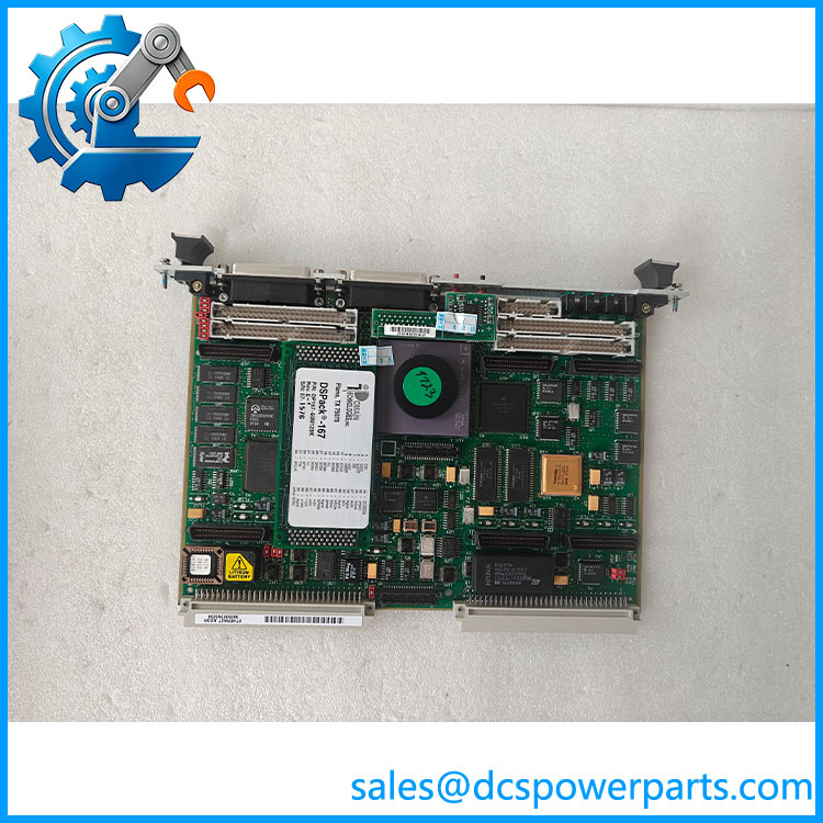
MVME162-513A
Major Features and Advantages
MC68040 processor architecture
The 32 MHz MC68040 provides a 32-bit processing platform with an integrated floating-point unit. This architecture supports embedded applications that depend on established Motorola 68K software and hardware interfaces. Retaining the same processor family can reduce the software migration work associated with replacing a legacy controller.
VMEbus system integration
The VMEchip2 provides the interface between the local processor bus and the VMEbus backplane. Its functions include bus mastering, system-controller operation, interrupt handling, and DMA transfers. These capabilities allow the controller to communicate with other VMEbus modules in a larger industrial or test-system chassis.
Integrated memory resources
The board combines 4 MB DRAM, 512 KB battery-backed SRAM, 1 MB Flash memory, and battery-backed NVRAM with a time-of-day clock. The SRAM and NVRAM support data retention and system configuration functions. Battery condition is an important inspection point on older boards because loss of backup power can affect retained data and clock operation.
Ethernet and SCSI interfaces
The documented -513A configuration includes both Ethernet and SCSI hardware. Ethernet supports network communication, while the SCSI interface provides access to compatible storage devices through DMA. Verify the installed controller chips and peripheral configuration rather than assuming every variant includes both interfaces.
Four IndustryPack expansion interfaces
Four IndustryPack interfaces provide expansion options for compatible I/O modules. This allows the embedded controller to support application-specific interfaces without requiring a separate processor board. Check the installed IndustryPack modules and their software drivers when transferring a board between systems.
Serial communication flexibility
The family provides two serial ports. The exact -513A configuration documented with SIMM06 uses an EIA-232-D DCE serial interface for Port B. Port configuration matters when connecting consoles, diagnostic terminals, or external control equipment. Confirm the transition module and cable wiring before startup.
On-board diagnostic and monitoring functions
The board includes front-panel indicators and ABORT/RESET pushbuttons. The 162Bug monitor provides board-level configuration and diagnostic functions. These features are useful during commissioning and fault isolation, particularly when the host operating system does not boot normally.
Related Products
- MVME-510A – Related 32 MHz MC68040 configuration; verify memory and peripheral options.
- MVME-511A – configuration with SCSI option.
- MVME-512A – configuration with Ethernet option.
- MVME-520A – Higher-memory 32 MHz configuration.
- MVME-523A – Higher-memory configuration with SCSI and Ethernet options.
- MVME712M – Transition module used with compatible P2 I/O arrangements.
- MVME712A – Alternative transition-module family member; check system-specific wiring.
- MEM162 – Memory expansion module for compatible configurations.
These are related family components or configurations. Verify the complete part number, installed options, and system requirements before treating any item as a replacement.
Frequently Asked Questions
Q1: What is the Motorola -513A used for?
It is a 6U VMEbus embedded controller used in industrial computing, real-time control, test equipment, and data acquisition systems. Its processor and peripheral interfaces support embedded applications that use the Motorola 68K architecture.
Q2: Which processor is insta the ?
The documented -513A configuration uses a 32 MHz processor with an integrated floating-point unit. Confirm the processor marking on the physical board when purchasing used stock.
Q the include Ethernet and SCSI?
Yes. The documented -513A configuration includes an Ethernet transceiver interface and an SCSI interface with 32-bit local-bus burst DMA. Verify the installed controller hardware and connectors on the specific board being supplied.
Q4: Can I replace another mod the ?
Not without checking the configuration. variants differ in processor, memory, Ethernet, SCSI, and serial-interface options. Compare the board identifier, artwork revision, installed peripherals, and software requirements before substitution.
Q5: Can I h the ?
Do not assume hot-swap capability. The is a VMEbus controller board, and removal can affect backplane operation and other installed modules. Follow the chassis manufacturer’s power-down and board-removal procedure.
Q the support firmware v3.1?
There is no universal v3.1 firmware compatibility specification for the board itself. The installed 162Bug monitor, application firmware, operating system, and system configuration determine software compatibility. Verify the actual firmware revision and boot environment.
Q7: What should I inspect before purchaused ?
Check the processor marking, board identifier, artwork revision, memory configuration, Ethernet and SCSI components, serial-port module, battery condition, and connector integrity. Request evidence of successful power-on testing, memory checks, VMEbus communication, and peripheral-interface testing where available.
Procurement and Quality-Control Notes
The is legacy VME computing hardware. For a replacement purchase, the exact board configuration is more important than the gMVME162 family designation.
Recommended receiving checks:
- Confirm the front-panel label and board idenread .
- Verify the processor and 32 MHz configuration.
- Check the installed 4 MB DRAM and 512 KB SRAM configuration.
- Inspect Ethernet and SCSI controller components.
- Verify the SIMM06 serial-interface configuration where required.
- Inspect the VMEbus P1/P2 connectors for bent contacts or oxidation.
- Check battery condition and retained configuration data.
- Request a documented power-on and functional test.
Procurement priority: Specirola , 32 MHz , 4 MB DRAM, Ethernet and SCSI configuration. Confirm the board artwork revision and installed firmware before approving it as a replacement.