Description
Key Technical Specifications
| Parameter | Value |
|---|---|
| Manufacturer | Metso Automation / Valmet |
| Model | IOP353 |
| Part Number | 181557 |
| Product Type | Digital Output Relay Driver Module |
| System Family | maxPAC / Metso DNA DCS |
| Output Channels | 16 channels |
| Output Type | Relay driver outputs |
| Output Voltage | 24 VDC |
| Maximum Channel Capacity | Approx. 100 mA @ 24 VDC |
| Isolation | Field-to-logic optical isolation |
| Output Indication | Individual channel status LEDs |
| Response Time | Approx. 1 ms maximum (excluding external relay) |
| Power Supply | 24 VDC system supply via module |
| Mounting | maxPAC I/O chassis |
| Application | Discrete field device control |
Product Introduction
Metso Automation IOP353 Overview
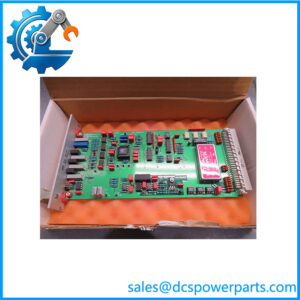
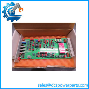
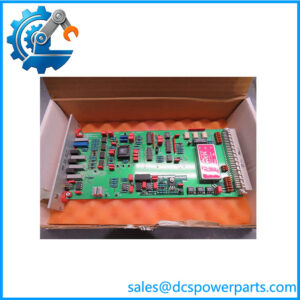
The Metso IOP353 is a 16-channel digital output relay driver module designed for the Metso maxPAC and Metso DNA distributed control system platforms. It provides the electrical interface between the DCS control logic and external discrete field devices, allowing the automation system to issue ON/OFF commands to plant equipment.
The Metso IOP353 181557 is primarily used where high-frequency switching of 24 VDC loads is required. Unlike mechanical relay output modules, the relay driver design provides faster switching response and avoids mechanical contact wear, making it suitable for applications involving frequent actuator commands, alarm outputs, and control interlocks.
The Metso IOP353 digital output module contains 16 independent output channels with individual status indication. Each channel provides feedback through front-panel LEDs, allowing maintenance personnel to quickly identify output activation status during commissioning and troubleshooting.
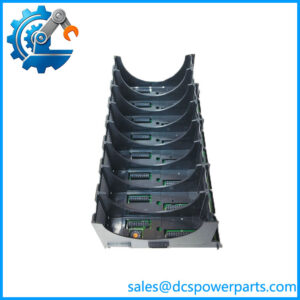
The Metso IOP353 relay driver module is installed as part of the maxPAC I/O architecture and communicates with the distributed processing unit through the internal I/O bus. It is not a standalone controller; correct operation depends on the DPU configuration, I/O database, field wiring, and application logic stored within the Metso DNA control system.
The is commonly found in long-life industrial installations where Metso automation systems continue operating for many years. Typical applications include valve control, motor starter interfaces, alarm annunciators, and sequence control functions.
When replacing a , engineers should verify the exact module type, I/O address configuration, field wiring arrangement, and control database settings. A physically compatible replacement without the correct configuration can result in incorrect output operation or unexpected process behavior.
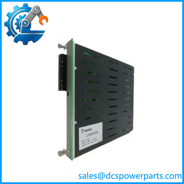
IOP353
Application Scenarios & Field Considerations
Engineering Pain Point
Common -related problems include:
- Field actuator not responding
- Output channel alarms
- Loss of relay driver signals
- Incorrect sequence operation
- Intermittent output activation
The module may be involved, but engineers should also inspect:
- 24 VDC system power
- Field wiring condition
- Interposing relays
- Solenoid coils
- DCS output configuration
Recommended troubleshooting steps:
- Check module active LED status
- Verify individual channel indicators
- Review Metso DNA diagnostics
- Measure output voltage at terminals
- Confirm field device resistance
- Compare I/O database configuration
The is one component in the complete control loop. Reliable operation depends on the interaction between the DCS processor, I/O module, wiring system, and controlled equipment.
Typical Applications
Valve and Actuator Control
Used for:
- Pneumatic valve solenoids
- Hydraulic control signals
- Process isolation valves
Pulp & Paper Automation
Applied for:
- Machine sequence control
- Auxiliary equipment operation
- Process interlocks
Power Generation Systems
Used for:
- Alarm outputs
- Equipment status control
- Auxiliary system commands
Industrial Process Plants
Applied in:
- Chemical processing
- Water treatment
- Manufacturing automation
Technical Pitfalls to Avoid
1. Confirm Module Type
Verify:
- relay driver function
- Correct maxPAC slot location
- Hardware revision
The is different from relay contact output modules such as IOP350 and IOP351.
2. Check Output Load Requirements
Confirm:
- Field device voltage
- Current consumption
- External relay requirements
- Protection components
3. Verify Power Supply Arrangement
Important checks:
- Use the correct 24 V system supply
- Confirm field wiring polarity
- Inspect power distribution
The design uses its own module output supply arrangement and does not support incorrect external supply configurations.
4. Preserve Existing Configuration
Before replacement:
- Record I/O channel assignments
- Save DCS configuration
- Document terminal wiring
- Capture diagnostic information
Related Products
- Metso IOP350
Form C relay output module used for higher switching capacity applications. - Metso IOP351
Form A/B relay output module with 16 relay channels. - Metso IOP330
Digital input module used for field status monitoring. - Metso IOP334
Isolated digital input module for industrial field signals. - Metso maxPAC DCS System
Distributed control hardware platform supporting I/O modules including the .