Description
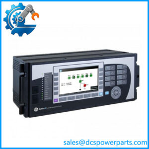
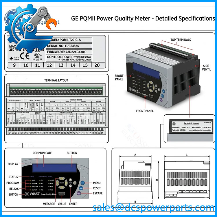
GE Multilin PQMII-T20-C-A
Key Technical Specifications
| Parameter | Specification |
|---|---|
| Product Model | PQMII-T20-C-A |
| Manufacturer | GE Multilin |
| Product Family | PQM II Power Quality Meter |
| Product Type | Power Quality / Electrical Monitoring Meter |
| T20 Option | Four isolated analog outputs, 0–20 mA / 4–20 mA |
| Analog Input | One isolated 4–20 mA input |
| Additional Communication | Second RS485 port |
| Control Option | Three additional programmable output relays |
| Switch Inputs | Four programmable switch inputs |
| Power Analysis | Harmonics, waveform capture, event recorder, data logger, voltage disturbance recorder |
| CT Inputs | 3 isolated phase CT inputs + 1 isolated neutral CT input |
| CT Secondary | 1 A or 5 A |
| VT Inputs | 0–600 V, 3-wire or 4-wire |
| Communications | RS485 / RS232 |
| Protocol | Modbus |
| Standard Control Power | 70–265 VAC, 50/60 Hz or 90–300 VDC |
| Contact Rating | Up to 250 VAC, 10 A resistive on documented configuration |
| Mounting | Panel mount |
| Processor | 25 MHz on later hardware revisions |
| Configuration Software | EnerVista PQM II Setup |
GE’s current PQM II manual identifies PQMII-T20-C-A as a complete option configuration. The T20 option adds four isolated analog outputs, a 4–20 mA analog input, and a second RS485 port; the C option adds three programmable output relays and four switch inputs; the A option provides the power-analysis functions.
The meter accepts three isolated phase CT inputs plus an isolated neutral CT input, with 1A or 5A CT secondary inputs. Voltage measurement supports up to 600V using either three-wire or four-wire connections. Standard control power is 70–265 VAC or 90–300 VDC.
Product Introduction
The GE Multilin PQMII-T20-C-A is a multifunction power quality meter intended for continuous monitoring of electrical distribution systems. It combines voltage, current, power, energy, power factor, demand, harmonic analysis, event recording, and data-logging functions with RS485/RS232 communications. The T20 configuration also provides isolated analog outputs for sending measured values directly to PLC, DCS, or other control equipment.
For an existing plant, the value of this configuration is its ability to combine measurement, alarming, control, and SCADA communications in one panel-mounted instrument. The PQMII-T20-C-A can also capture waveform and power-quality information that is useful when investigating nuisance breaker trips, transformer heating, capacitor problems, or abnormal loads.
PQMII-T20-C-A
Application Scenarios & Field Pitfalls — The Engineer’s Perspective
Engineering Pain Point
A power-quality problem is often intermittent: a voltage disturbance may disappear before an electrician reaches the panel, while a harmonic-related heating problem may only appear under a particular production load. The PQMII-T20-C-A addresses this by combining normal electrical measurements with event recording, harmonic analysis, waveform capture, and data logging. The key during replacement is preserving the original CT/VT configuration and communications mapping rather than treating the unit as a generic power meter.
Typical Applications
- Industrial switchgear monitoring — continuous current, voltage, power, demand, and power-factor measurement.
- Manufacturing plants — investigation of voltage disturbances, harmonics, abnormal loading, and nuisance protection events.
- Motor and drive installations — monitoring electrical conditions associated with large motors and variable-frequency-drive loads.
- PLC/DCS integration — transmission of selected measured parameters through 4–20 mA outputs or Modbus communications.
Technical Pitfalls to Avoid
- Verify the exact CT configuration before energizing the replacement.
The PQM II uses three phase CT inputs plus a neutral CT input and supports 1A or 5A CT secondaries. A mismatch here is not a software configuration detail; it directly affects measurement accuracy and installation safety. - Do not assume every PQM II has the same hardware options.
The model suffix defines the installed option package. In T20-C-A, T20, C, and A are meaningful hardware/function selections, not cosmetic suffixes. The exact order code should be compared with the original meter label. - Check processor revision when relying on voltage disturbance recording.
GE documentation states that the voltage disturbance recorder requires the 25 MHz processor. Older PQM II hardware can use a 16 MHz processor, so the presence of the “A” option alone should not be treated as proof that every advanced recording function is available. - Preserve the Modbus register mapping during replacement.
Existing SCADA or PLC logic may read specific PQM II registers for current, voltage, power, demand, power factor, harmonic data, alarms, and status. A hardware replacement should therefore include a communications checkout, not just a power-up test.
Related Products
- PQMII-T20 — PQM II configuration with the T20 transducer option; useful when additional control and power-analysis functions are not required.
- PQMII-T1 — alternative transducer configuration using 0–1 mA analog outputs rather than the T20 0–20/4–20 mA arrangement.
- PQMII-C — control-oriented configuration with additional programmable relays and switch inputs.
- PQMII-A — power-analysis configuration for harmonic analysis, waveform capture, event recording, and related diagnostics.
- PQMII-T20-A — combines the T20 analog-transducer functions with the A power-analysis package without the additional C control option.
- PQMII-T1-C-A — combines the T1 transducer option with control and power-analysis functions; relevant where legacy 0–1 mA interfaces must be retained.
- PQMII-C-A — control plus power-analysis configuration without the T20 analog-output package.
- PQM II — base meter configuration with the core electrical measurement and communications functions.
GE’s ordering documentation confirms that these suffixes represent distinct PQM II option combinations, so an apparently similar model should not be substituted until the existing analog interface, relay configuration, communications requirements, and power-analysis functions have been checked.