Description
Product Introduction
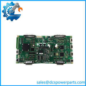
A failed communication board in an excitation system can be mistaken for a controller, feedback, or fiber-network problem because several signal paths converge at the same point. The GE IS200EISBH1A is the EISB, or Exciter ISBus Board, used in the EX2100 excitation control architecture. Its job is to receive and transmit excitation-related feedback signals, pass information through the control backplane toward the DSPX controller, and provide communication paths associated with the M1, M2, and C control modules.
The GE IS200EISBH1A is a 3U single-slot board installed in the EX2100 control rack beneath the DSPX. Six fiber-optic connectors provide dedicated signal paths associated with generator-field voltage/current, optional exciter voltage/current, and ground-detector signals. The board also handles RS-232C communication between the DSPX and tool/keypad interfaces. This makes the EISB a system-interface component rather than a conventional analog or digital I/O card.
Key Technical Specifications
| Parameter | Specification |
|---|---|
| Product Model | IS200EISBH1A |
| Manufacturer | General Electric |
| Product Series | EX2100 Excitation Control |
| Board Designation | EISB |
| Product Type | Exciter ISBus / communication interface board |
| Primary Function | Excitation feedback and controller communication |
| Controller Compatibility | M1, M2, C controllers |
| Form Factor | 3U |
| Slot Occupancy | Single slot |
| Front Fiber Interfaces | 6 |
| Serial Interface | RS-232C |
| Backplane Interface | Control backplane to DSPX |
| ISBus | GE proprietary excitation-system communication |
| Front Indicators | 6 status indicators |
| Installation Location | Control rack beneath DSPX |
| Manual Reference | GEI-100454 |
| Typical System | GE EX2100 excitation control |
Published technical descriptions agree on the board’s EISB function, 3U/single-slot form factor, six front-panel fiber connections, RS-232C tool/keypad communication, and installation beneath the DSPX controller.
Some secondary catalog records also list 4–20 mA signal specifications, ±5 V common-mode range, 15 Ω maximum lead resistance, and 0–20 mA analog output information. Those details appear inconsistently across reseller databases and should therefore be verified against the GEI-100454 documentation and the exact board revision before being used for electrical design.
Application Scenarios & Pain Points
The EISB becomes important when troubleshooting an EX2100 system in which excitation feedback or controller communication is intermittent. The board sits at the intersection of several signal paths, so a fault here can produce symptoms that appear elsewhere in the excitation system.
- EX2100 excitation control: Provides the ISBus communication interface used by the excitation control architecture.
- Generator-field feedback: Interfaces fiber-optic feedback associated with generator-field voltage and current measurements.
- Exciter feedback: Provides optional signal paths for exciter voltage and current feedback.
- Ground detection: Interfaces signals associated with the ground-detection module, including voltage input/output paths.
- Controller communications: Connects the EISB to M1, M2, and C controllers and communicates with the DSPX through the control backplane.
Field note: If an system suddenly reports multiple excitation-feedback abnormalities at once, do not immediately replace the DSPX or field-feedback boards. First determine whether the common communication path through the EISB, its fiber connections, and its backplane connection is healthy.
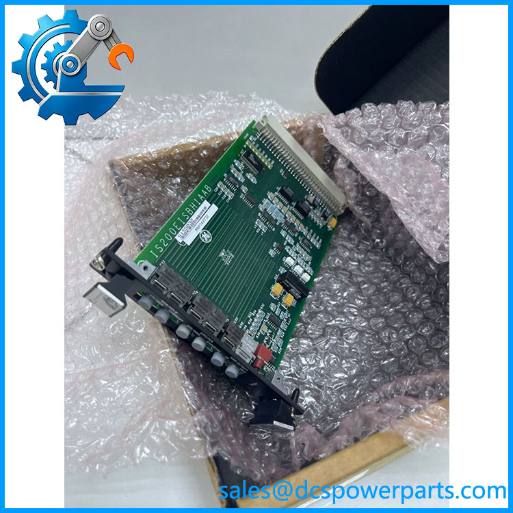
IS200EISBH1A
Related Products
- GE IS200DSPXH1D — DSPX controller board; the EISB communicates with the DSPX through the control architecture.
- GE IS200EDCFG1A — DC feedback board associated with generator-field measurement signals.
- GE IS200EGDMH1A — ground-detection module used with the EISB signal path.
- GE IS200EMIOH1A — main I/O board for broader system I/O functions.
- GE IS200EPSMG1A — excitation power-supply board.
- GE IS200ECTBG1A — terminal board used for field wiring/interface functions.
- GE IS200EPCTG1A — excitation-related interface/control board.
- GE IS200EISBH — Base EISB board designation associated with the same function.
- GEI-100454 — Technical documentation specifically associated with the EISB board.
These components are related to the same excitation architecture, but they perform substantially different functions. In particular, the EISB should not be substituted with the DSPX, EMIO, EDCF, or EGDM merely because all appear in the same control rack.
Engineer’s Guide — Field Pitfalls to Avoid
1. Do not confuse EISB with DSPX
The IS200EISBH1A is an interface/communication board, not the main DSPX controller.
Avoidance: Trace the actual signal path before replacing hardware. If multiple feedback channels disappear simultaneously, investigate the common EISB path.
2. Inspect all six fiber-optic connections
The six front-panel optical interfaces have defined roles. They are not interchangeable simply because the connectors look similar. Published descriptions associate them with generator-field, exciter, and ground-detector signal paths.
Avoidance: Photograph and label every fiber connection before removing the original board. Maintain the original port-to-port mapping.
3. Do not treat a fiber fault as a board fault
Dirty optical connectors, damaged fiber, excessive bend radius, or incorrect port assignment can produce symptoms very similar to an EISB failure.
Avoidance: Inspect optical connections and verify signal continuity before condemning the PCB.
4. Check the board revision carefully
The supplied designation is IS200EISBH1A. Some records refer to a longer revision identifier such as IS200EISBH1AAC.
Avoidance: Photograph the complete board label and revision markings when sourcing a replacement. Do not approve a substitute from the shortened base number alone.
5. Protect the board from ESD
The EISB contains communication electronics and fiber-optic interface circuitry.
Avoidance: Use proper ESD handling, keep the PCB in its protective packaging until installation, and avoid touching board components or connector contacts unnecessarily.
6. Check the backplane connection
The board depends on its control-rack/backplane connection to communicate toward the DSPX and the rest of the excitation-control architecture.
Avoidance: Inspect the card guides, backplane connector, mounting position, and signs of oxidation or mechanical damage before declaring the PCB defective.
FAQ
What is GE IS200EISBH1A?
The is an Exciter ISBus Board (EISB) used in GE excitation control systems. It provides communication and signal-interface functions between the excitation feedback circuits, controllers, DSPX, and ground-detection system.
What does the EISB board do in an system?
It handles excitation-system communication and feedback interfaces. The board receives/transmits fiber-optic signals and passes information through the control backplane toward the DSPX controller. It also supports communication involving the M1, M2, and C controllers.
How many fiber-optic connections does have?
Published technical descriptions identify six front-panel fiber-optic connectors. Their functions include generator-field voltage/current feedback, optional exciter voltage/current feedback, and ground-detector signal paths.
Where is installed?
It is installed as a 3U, single-slot board in the control rack beneath the DSPX controller.
Does use RS-232?
Yes. The board provides RS-232C communication associated with the tool and keypad ports, in addition to its ISBus and fiber-optic functions.
Is an I/O board?
Not in the conventional PLC sense. Its primary designation is Exciter ISBus Board, and its principal role is communications and signal interfacing within the excitation system. Do not treat it as a general-purpose analog or digital I/O module.
What should I verify before purchasing a replacement ?
Verify the complete part number and revision, system compatibility, six fiber-port arrangement, board condition, connector condition, and backplane interface. If the existing board is being replaced because of a system fault, also check the associated EDCF, EGDM, DSPX, fiber-optic cables, and power/grounding conditions before installing the replacement.
Is compatible with GE Mark VI systems?
The board is associated with GE’s excitation control architecture, which can be integrated into GE turbine control environments. Some supplier records categorize it under Mark VI because of the broader Speedtronic platform relationship. The safer procurement criterion is the EISB function and exact hardware revision, rather than the generic Mark VI label.