Description
Key Technical Specifications
| Parameter | Specification |
|---|---|
| Product model | DS200VPBLG2A |
| Manufacturer | GE |
| Functional acronym | VPBL |
| Product category | VME P2 backplane board |
| System platform | LS2100 LCI static starter |
| Bus architecture | VME |
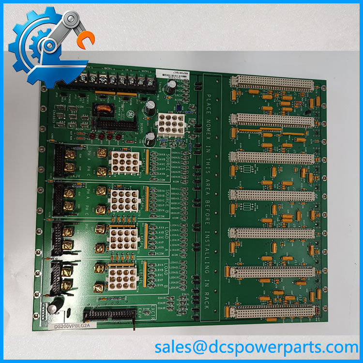
| VME connector count | 8 |
| Connector arrangement | Six double-spaced positions and two single-spaced positions, as described in supplier documentation |
| Exciter connector | 34-pin ribbon connector |
| Power connector | 12-pin Mate-N-Lock, JAA |
| Backplane interconnection | Ten power connection points, referred to as power bugs in the product documentation |
| Manual reference | GEI-100227 |
| Operating temperature | A supplier listing reports 0°C to +60°C; confirm against the applicable GE documentation |
| Supply voltage | System-level input rating not independently verified |
| Protection rating | Not verified |
| Mounting | Internal control-assembly backplane; confirm the original chassis arrangement |
The connector count, exciter connector, power connector, and manual reference are supported by model-specific product records. The operating temperature comes from supplier documentation rather than an independently verified manufacturer datasheet. Do not interpret it as a complete environmental qualification.
Major Features and Advantages
VME board interconnection
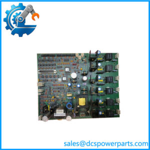
The DS200VPBLG2A provides the backplane connections used by compatible boards in the LS2100 control assembly. Backplane integrity matters because poor contacts, damaged traces, or incorrect connections can interrupt communication between installed control hardware.
Dedicated exciter connection
The board includes a 34-pin ribbon connector identified as EXJV in the product documentation. This connection is associated with external exciter signals. When replacing the board, confirm the ribbon cable orientation, connector condition, and original routing before reconnection.
DS200VPBLG2A
Multiple board positions
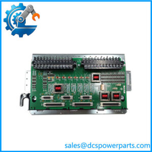
The eight VME-type connectors support the documented board arrangement, including six double-spaced positions and two single-spaced positions. This layout is specific to the backplane assembly; it should not be treated as evidence that every standard VME board is electrically compatible with the LS2100 system.
Dedicated power interconnection
The 12-pin Mate-N-Lock connector provides the documented power connection, while the board’s power connection points interface with the associated backplane arrangement. Verify the wiring diagram and connector pinout before installation. Do not infer the board’s supply voltage from the connector type alone.
Legacy control-system maintenance
For an existing LS2100 installation, a matching replacement backplane may help retain the original board arrangement and wiring architecture. Procurement should focus on the complete part number, revision, connector condition, and evidence of electrical inspection rather than appearance alone.
Application Scenarios and Common Pain Points
- LS2100 static starter maintenance: Replacing a damaged backplane in the original control assembly.
- VME control-system restoration: Restoring board-to-board interconnections in an established VME-based system.
- Exciter interface maintenance: Inspecting the backplane and its ribbon connection when external exciter signaling is interrupted.
- Spare-parts planning: Maintaining a verified spare for legacy equipment where the original chassis and wiring must be retained.
- Fault investigation: Checking for connector damage, cracked solder joints, contamination, or electrical faults that could affect multiple installed boards.
Common problems include ordering a processor board instead of the backplane, confusing the G1A and G2A revisions, overlooking the 34-pin exciter cable, and assuming that a standard VME form factor guarantees system compatibility.
Related Products
The following parts are related to the same control-system hardware family or board function. They are not confirmed direct substitutes for DS200VPBLG2A.
| Model | Product description | Relationship |
|---|---|---|
| DS200VPBLG1A | GE VPBL VME backplane board | Earlier related revision; confirm revision-specific compatibility |
| DSPC board | Processor/control board referenced in the LS2100 backplane documentation | Installed board supported by the backplane arrangement |
| Gate Distribution Status Board (FCGD) | Gate distribution status board | Related control-system hardware |
| I/O extender daughterboard | I/O expansion interface | Supported board type within the documented arrangement |
| Exciter board | Excitation-control hardware | Associated with the dedicated exciter connection |
The DS200VPBLG1A is the closest model-number comparison identified in the available records. Even so, revision differences must be checked against the original system documentation before substitution.
Engineer’s Guide: Three Checks Before Installation
1. Verify the board identity and revision. Match DS200VPBLG2A against the installed board’s label and the equipment records. Do not assume DS200VPBLG1A and DS200VPBLG2A are interchangeable without documented approval.
2. Inspect every connection. Check the VME connectors, 34-pin exciter ribbon connector, 12-pin power connector, and backplane contact points. Record cable positions before removing the original board.
3. Follow the approved isolation and commissioning procedure. Isolate power sources and follow the site’s electrical safety procedure before removing or installing the backplane. After installation, verify connector seating, board positions, power distribution, and system diagnostics before returning the static starter to service.
Frequently Asked Questions
Q1. What is the GE DS200VPBLG2A?
It is identified as a VME P2 backplane board for the GE LCI static starter control system.
Q2. Is a processor board?
The more consistent model-specific records identify it as a backplane, not a processor or bus-master board. Some supplier listings use inconsistent descriptions, so verify the physical board marking and system documentation.
Q3. How many VME connectors does it have?
Product-specific listings report eight VME connectors, arranged as six double-spaced positions and two single-spaced positions. Confirm the layout against the actual board before fitting other hardware.
Q4. What connectors are used?
The documented connectors include a 34-pin ribbon connector for the exciter connection and a 12-pin Mate-N-Lock power connector designated JAA. Verify the exact pinout using the applicable manual.
Q5. Can DS200VPBLG1A replace ?
Not automatically. The G1A is a related backplane revision, but the available evidence does not establish unrestricted interchangeability. Check GEI-100227 and the equipment configuration before substitution.
Q6. What should be checked when purchasing a used board?
Request photographs of the complete part number, revision markings, connector faces, and PCB condition. Ask for inspection and continuity-test evidence, warranty terms, and confirmation that the board was checked for damage to its backplane contacts and power connections.
Q7. What are the warranty and lead time?
These depend on the supplier and the individual unit. Confirm stock status, dispatch timing, warranty duration, return conditions, and the scope of testing in writing.
Procurement recommendation: Treat as a dedicated VME P2 backplane, not a generic processor board. Verify the G2A revision, connector layout, exciter ribbon connection, and power wiring against the original assembly before approving a replacement.