Description
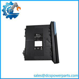
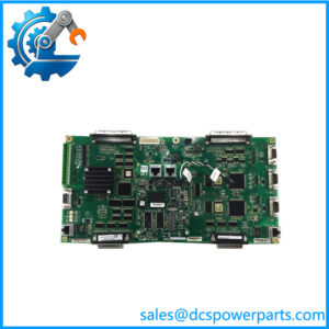
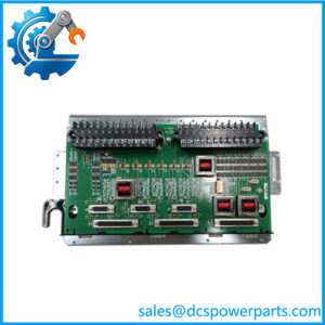
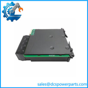
GE DS200TCRAG2A
Key Technical Specifications
| Parameter | Specification |
|---|---|
| Product Model | DS200TCRAG2A |
| Manufacturer | General Electric |
| Product Family | Mark V / Mark V LM |
| Functional Acronym | TCRA |
| Product Type | Relay Output Terminal Board |
| Functional Revision | A |
| Relay Quantity | 30 |
| Relay Designations | K1–K30 |
| Relay Contact Rating | 0.5 A per relay, according to available technical records |
| Compatible Core Positions | Q11 and Q51 |
| Control Signal Interface | JO connector |
| Field Output Connections | JS1–JS8 |
| Associated Terminal Boards | DTBC / DTBD |
| Additional Connectors | JOR, JOS, JOT; typically not used |
| Power Connectors | J19, J20 on applicable configurations |
| Software Configuration | None on the TCRA board |
| Hardware Configuration | Associated DTBC/DTBD terminal-board jumpers |
| Primary Application | GE turbine control digital output circuits |
The DS200TCRAG2A contains 30 plug-in relays designated K1 through K30. Available technical documentation identifies it as a TCRA relay-output terminal board used in the Mark V Q11/Q51 digital I/O architecture.
Product Introduction
The GE DS200TCRAG2A is a Mark V TCRA relay output terminal board used to interface digital control commands with relay-based field outputs. The board is installed in the Mark V digital I/O cores and uses individual relays to switch output circuits associated with turbine auxiliaries, solenoids, valves, and other controlled devices. The board itself does not execute the turbine control application; it provides the relay interface between Mark V I/O electronics and field termination circuitry.
The board carries 30 relays, K1 through K30. Its exact use depends strongly on the core location and Mark V cabinet configuration. In documented Q11 applications, only four relays may be used for gas-manifold blow-off valve control, while other TCRA installations can use substantially more relay channels for solenoid-related output circuits.
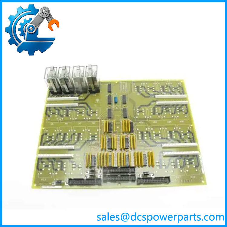
DS200TCRAG2A
Application Scenarios & Field Pitfalls — The Engineer’s Perspective
Engineering Pain Point
The critical issue with a TCRA replacement is that relay count does not tell you which relay circuits are actually used. The DS200TCRAG2A has 30 relay positions, but the active circuits depend on whether the board is installed in Q11, Q51, or another documented position within the Mark V architecture. The associated DTBC/DTBD boards also determine how certain relay outputs are configured.
Typical Applications
- Gas turbine auxiliary control — relay outputs for valves and other discrete turbine auxiliaries.
- Gas manifold blow-off valve circuits — documented Q11 applications use four TCRA relays for this function.
- Solenoid output circuits — selected relay groups can be configured to provide the required field-side switching or power source.
- Mark V LM digital I/O cores — used in the Q11/Q51 architecture as part of the relay-output path.
Technical Pitfalls to Avoid
- Verify the core location before replacement.
A TCRA board’s function changes according to where it is installed. Do not assume a board from one core has the same active relay assignments as another. - Do not treat all 30 relays as active field outputs.
The board has 30 relay positions, but documented Q11 configurations can use only four relays for specific blow-off valve applications. Other configurations use additional relay groups. - Check DTBC/DTBD jumper configuration.
The field-side configuration for certain relay outputs is implemented through hardware jumpers on the associated terminal boards. Replacing the TCRA without documenting those settings can create a functional mismatch. - Preserve JO and JS wiring.
The JO connection carries relay-control signals from the associated Mark V I/O electronics, while JS1–JS8 carry relay outputs toward the DTBC/DTBD terminal boards. - Inspect J19/J20 if used.
Technical documentation identifies these as additional power connections in applicable configurations, including circuits associated with ignition-transformer applications. Verify the cabinet drawings before disconnecting them. - Do not confuse TCRA with a generic relay module.
The board’s electrical role is defined by its position within the Mark V digital I/O architecture. A relay board with the same number of channels is not automatically a substitute.
Related Products
- DS200TCRAG1A — related Mark V relay output board; different TCRA hardware designation and should not be assumed interchangeable with the G2A version.
- DS200TCRAG2ABC — extended designation associated with the DS200TCRAG2A family; verify the complete PCB identification before substitution.
- TCDA — Mark V digital I/O board that supplies relay-control signals to the TCRA through the appropriate interface.
- TCQE — associated Mark V I/O board providing signals for TCRA boards in specific core positions, including documented Q11 applications.
- DTBC — Mark V terminal board associated with TCRA relay-output configuration and field connections.
- DTBD — related terminal board used with TCRA outputs and hardware configuration.
- DS200TCTGG1A — Mark V simplex trip board serving a different turbine protection/trip function; not a TCRA substitute.
- DS200TCQEG2A — Mark V LM6000 I/O processor board with a different processing role from the TCRA relay interface.
Procurement Note
For a replacement, specify the complete designation and record the board revision, core location, relay population actually in service, JO/JS connector wiring, and associated DTBC/DTBD jumper configuration.
The important distinction is that is a relay-output interface board, not a programmable controller. Its behavior is determined by the Mark V architecture and associated hardware. Before energizing a replacement, verify every field output against the approved Mark V wiring drawings and the installed relay configuration.