Description
Key Technical Specifications
| Parameter | Specification |
|---|---|
| Product Model | DS200TCCBG1BED |
| Manufacturer | General Electric |
| Series | Mark V Speedtronic |
| Functional Acronym | TCCB |
| Product Type | Common Extended Analog I/O Board |
| Functional Description | Extended Analog I/O |
| Functional Revision 1 | B |
| Functional Revision 2 | E |
| Artwork Revision | D |
| PCB Coating | Normal coating |
| Processor | Intel 80196 |
| Firmware Storage | Multiple PROM modules |
| Board LED | 1 |
| Primary Signal Types | 4–20 mA / 0–1 mA, RTD, PT/CT-related signals |
| 50-Pin Connectors | JCC and JDD |
| Primary Interface Connectors | 2PL, 3PL, JHH, JII, JMP |
| Hardware Jumpers | J1–J5, J14; J15/J16 associated with testing |
| System | GE Mark V Turbine Control |
The DS200TCCBG1BED is documented as the Common Extended Analog I/O Board (TCCB). Its circuitry provides scaling and conditioning for additional analog signals received from the TBCB terminal board and TCEB board. Documented signal groups include 4–20 mA/0–1 mA inputs, RTDs, generator and bus voltage signals, and line-current signals.
Product Introduction
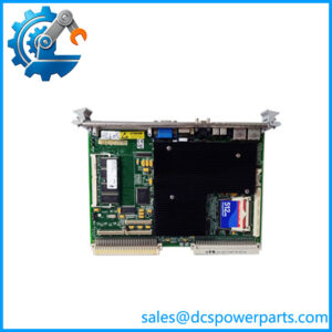
The GE DS200TCCBG1BED is a Common Extended Analog I/O Board used in GE Mark V Speedtronic turbine control systems. The TCCB is part of the controller’s internal analog signal-processing architecture rather than a general-purpose PLC analog card. It receives field-related signal information from associated terminal and protective-interface boards, performs scaling and conditioning, and passes the processed information into the Mark V control system.
The board contains an Intel 80196 microprocessor, multiple PROM modules, a board-mounted LED, and multiple dedicated connectors. The exact G1BED revision is important during replacement because connector assignments, jumper configuration, PROM hardware, and the host Mark V architecture all have to be considered together.
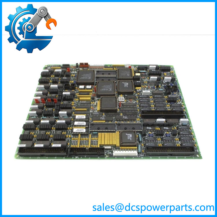
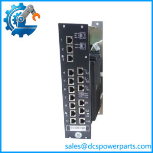
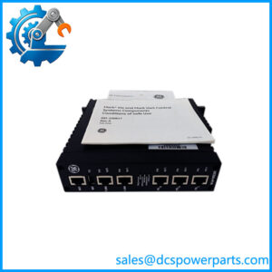
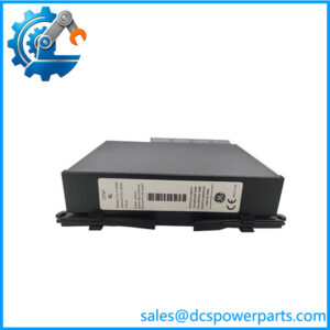
DS200TCCBG1BED
Application Scenarios & Field Pitfalls — The Engineer’s Perspective
Engineering Pain Point
A TCCB fault can look like a field transmitter, RTD, PT/CT, or terminal-board problem because the board sits in the signal-conditioning path. Replacing the PCB without first identifying which signal group is actually failing can lead to unnecessary board swaps. The Mark V signal architecture gives useful diagnostic clues: JHH is associated with mA inputs from TBCB, JII with RTD signals, and JMP with PT/CT signals from TCEB.
Typical Applications
- 4–20 mA and 0–1 mA signal processing: The TCCB receives additional analog inputs from the TBCB terminal-board circuitry.
- RTD monitoring: RTD signals are routed through the TCCB architecture via the JII interface.
- Generator and bus voltage monitoring: Hardware jumpers J1–J5 are associated with generator/bus voltage and line-current monitoring functions in documented Mark V LM configurations.
- PT/CT signal processing: The JMP interface carries PT and CT-related signals from the TCEB board into the TCCB.
Technical Pitfalls to Avoid
- Do not treat DS200TCCBG1BED as a generic analog input card. Its signal paths are tied to the Mark V architecture, terminal boards, protective circuitry, and controller configuration.
- Verify the entire part number. DS200TCCBG1BED identifies a specific combination of functional and artwork revisions. Ordering a board based only on “TCCB” or “DS200TCCB” is insufficient for a controlled replacement.
- Record PROM modules before replacement. Secondary technical documentation states that PROM modules are part of the board’s firmware storage and may need to be transferred when replacing certain versions. Confirm the procedure against the applicable Mark V documentation before moving any PROM devices.
- Map ribbon cables by connector ID, not physical position. Board component layouts can differ between revisions, while connector identifiers remain the practical reference for reconnecting the wiring. Incorrect ribbon-cable placement can introduce multiple secondary faults.
- Check jumper settings before energization. J1–J5 have documented monitoring functions, while J14 is associated with the RS232/DCOM connection. Do not assume the replacement board’s jumper positions should be left at factory defaults.
- Do not copy conflicting reseller specifications into engineering documents. Several secondary listings publish different operating-voltage, temperature, and analog-output figures for this board. Those values should be verified against GE documentation for the installed Mark V configuration rather than treated as universal DS200TCCBG1BED ratings.
Related Products
- DS200TCEB — Protective Termination Expander Board; provides PT/CT-related signals that interface with the TCCB through the documented JMP path.
- DS200TBCB — Mark V terminal-board family associated with mA and RTD field signal inputs feeding the TCCB architecture.
- DS200STCA — Mark V control-core board receiving conditioned signal information through the core data architecture associated with the TCCB.
- DS200TCCA — Mark V Common Analog I/O board used alongside other core analog-processing boards; function and exact signal assignments must be checked before substitution.
- DS200PTBA — Protection termination board associated with Mark V protection-related field connections; it is not a direct substitute for the TCCB.
- DS200TCPS — Mark V power-supply board serving a different power-system function within the control core.
- DS200TCPD — Mark V power-distribution board; electrically and functionally different from the TCCB.
- DS200TCCB — Base TCCB family designation. The complete suffix remains necessary when establishing replacement compatibility.
Procurement and Replacement Note
For a replacement, record the complete board label, including G1BED, before procurement. Also document the Mark V controller configuration, cable locations, jumper positions, PROM identification, and the terminal boards connected to JHH, JII, and JMP.
One important procurement issue is the PROM hardware. If the installed board contains application-specific PROM devices, do not assume that a visually similar replacement board contains identical firmware. Confirm the required PROM arrangement and replacement procedure against the applicable GE Mark V documentation before transferring components.
For troubleshooting, isolate the signal category first—mA, RTD, generator/bus voltage, or CT-related input—then trace the associated terminal board, cable, TCCB connector, jumper configuration, and downstream COREBUS path. That approach is more reliable than treating every analog-value fault as a failed TCCB.