Description
GE DS200PTBAG1
Key Technical Specifications
| Parameter | Specification |
|---|---|
| Product Model | DS200PTBAG1 |
| Manufacturer | General Electric |
| Product Family | Mark V / SPEEDTRONIC |
| Functional Acronym | PTBA |
| Product Type | Protection Termination Module |
| Application | Turbine protection/control |
| Core Location | Protective P core / independent protection module |
| Associated Board | TCEB |
| Trip Interface | TCTG |
| Speed Signal Interface | TCQE |
| Main Signal Types | Shaft speed, flame detection, generator/bus voltage, generator current, trip and breaker signals |
| Terminal Blocks | 2 documented terminal blocks, TB1 and TB2 |
| Terminal Capacity | 72 signal-wire terminals per terminal block on documented A revision |
| Ribbon/Board Connectors | JJR, JJT, JJS on documented A revision |
| Hardware Jumper | Horn/audible-alarm enable function |
| Board Dimensions | Approx. 3 × 11.5 in. on documented A revision |
| Functional Revisions | A and B versions documented |
| System Architecture | Mark V turbine control |
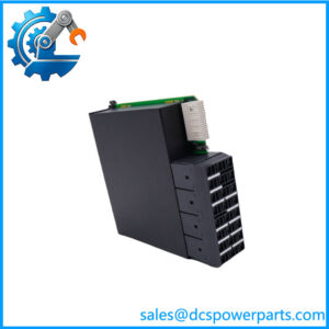
The documented DS200PTBAG1A version contains two terminal blocks, each accommodating 72 signal-wire positions, plus three 10-pin connectors identified as JJR, JJT, and JJS. Its PTBA connections handle protection-related signals including shaft-speed pickups, flame detection, generator/bus voltage and current, and trip interfaces.
Product Introduction
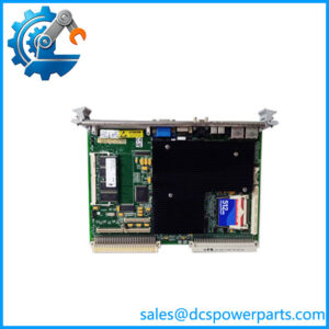
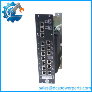
The GE DS200PTBAG1 is the base designation for a Mark V PTBA Protection Termination Board used in the protective portion of GE SPEEDTRONIC turbine control systems. The board provides the physical termination and routing point for critical protection signals before they are processed by associated Mark V control and protection circuitry. It is therefore an interface board, not the primary processor responsible for executing the turbine protection logic.
The PTBA interfaces with several important parts of the protective core. Documented connections include shaft-speed signals, flame detection, generator and bus voltage/current signals, external trip inputs, emergency trip outputs, and generator-breaker signals. The board also provides a hardware jumper associated with the TCEB audible alarm circuit.
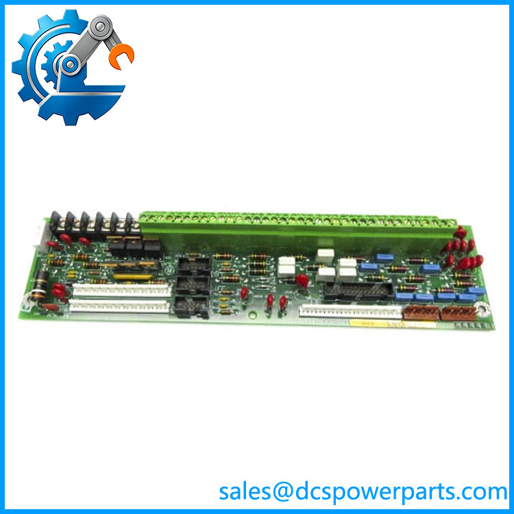
DS200PTBAG1
Application Scenarios & Field Pitfalls — The Engineer’s Perspective
Engineering Pain Point
The real replacement risk with DS200PTBAG1 is not the PCB itself; it is the large amount of safety-related field wiring attached to the PTBA. A documented A-revision board has two large terminal blocks and multiple inter-board connectors. A wiring error can move a legitimate protection signal to the wrong circuit or interrupt an existing trip path. GE Mark V documentation therefore makes terminal identification and careful wire mapping a critical part of board replacement.
Typical Applications
- Gas turbine protection systems — termination of shaft-speed, flame, generator, and protective trip signals.
- Steam turbine control systems — interface between field protection wiring and the Mark V protective core.
- Mark V LM installations — PTBA is located in the protective core and interfaces with TCEB/TCTG-related circuitry.
- Legacy turbine maintenance — replacement of aging PTBA hardware while retaining the installed Mark V architecture.
Technical Pitfalls to Avoid
- Do not order only from
DS200PTBAG1.
First inspect the complete PCB identification.DS200PTBAG1AandDS200PTBAG1Bare documented revisions of the PTBA family. - Map every terminal before disconnecting wiring.
The documented A version uses TB1 and TB2. Record the terminal number together with the wire identification rather than relying on memory or cable color. - Do not confuse PTBA with TCTG or TCEB.
PTBA provides termination and signal routing. TCTG and TCEB perform different functions within the protective core. - Pay particular attention to speed-pickup wiring.
PTBA is associated with turbine shaft-speed signals used by the Mark V overspeed protection architecture. Wiring polarity, shielding, and termination should be checked against the plant drawings before recommissioning. - Check the horn jumper.
The documented PTBA design includes a hardware jumper associated with the audible alarm/horn circuit. Do not copy its position blindly; verify the plant’s intended alarm configuration. - Do not assume an A-to-B revision swap is automatically approved.
A later functional revision may be physically similar but still require verification against the Mark V application, wiring, and associated boards.
Related Products
- DS200PTBAG1A — documented A-revision PTBA Protection Termination Module with the two large terminal blocks and protection-core signal interfaces.
- DS200PTBAG1B — B-revision PTBA Protection Termination Module; verify revision-specific compatibility before substituting for an A revision.
- TCEB — associated Mark V board receiving and transmitting several protection-related signals through the PTBA interface.
- TCTG — turbine trip board associated with emergency/external trip and generator-breaker signal paths through PTBA.
- TCQE — associated Mark V board receiving shaft-speed signals routed through the PTBA.
- DS200PTCTG1A — Mark V PTCT signal-conditioning board associated with the turbine-control/protection architecture; it is not a PTBA replacement.
- DS200QTBAG1A — Mark V QTBA termination board serving a different termination function from PTBA.
- DS200RTBAG1A — Mark V relay/termination board with a different functional role.
Procurement Note
For an actual replacement request, specify the complete board identification printed on the PCB, not just DS200PTBAG1. If the installed unit is marked DS200PTBAG1A, DS200PTBAG1B, or a longer assembly designation, retain that complete code in the purchase specification.
Before removing the old board, document TB1/TB2 terminal assignments, JJR/JJT/JJS connections, PT/CT wiring, shaft-speed pickup wiring, trip wiring, breaker wiring, and the horn-jumper position. The PTBA is part of the Mark V protection signal path, so functional testing after replacement should be based on the plant’s approved commissioning procedure rather than a simple power-up check.