Description
GE DS200NATOG2A Product Information
Product Overview
Voltage feedback in a load-commutated inverter (LCI) starter must be scaled correctly before the control system can use it. The GE DS200NATOG2A is a voltage feedback scaling board used in the GE LS2100 static starter system. Its NATO functional designation identifies its role in attenuating AC and DC voltages associated with the silicon-controlled rectifier (SCR) bridge. Rather than executing PLC logic or serving as a general-purpose communications interface, the board conditions voltage signals for feedback monitoring and control within the power-conversion assembly.
The circuit contains five resistor strings: three assigned to AC phases and two for the positive and negative DC bus. Each string includes selectable input connection points and jumper positions to accommodate specified voltage ranges. The resulting signals pass through a single 20-pin ribbon header. Metal oxide varistors (MOVs) provide protection against excessive output voltage under the documented ribbon-circuit interruption condition. The burden resistors required for operation are located on the associated gate distribution and status board, not on the NATO board itself. That distinction matters when diagnosing unexpected feedback readings.
For maintenance teams managing an LS2100 static starter, the GE DS200NATOG2A is relevant to voltage-feedback troubleshooting, scheduled board replacement, and legacy equipment spare-parts planning. The G2 configuration differs from the G1 version in its resistor and jumper arrangement, so a similar model number is not enough to approve a substitution. Before fitting a replacement, check the full part number, input stab positions, jumper configuration, ribbon connection, and installed system voltage against GEI-100225. The board’s configuration must match the application; changing the attenuation arrangement without engineering verification can produce incorrect feedback signals.
Key Technical Specifications
| Parameter | Value |
|---|---|
| Manufacturer | General Electric (GE) |
| Product Model | DS200NATOG2A |
| Functional Acronym | NATO |
| Product Type | Voltage Feedback Scaling Board |
| Product Series | LS2100 Static Starter Control |
| Primary Function | AC/DC voltage attenuation and feedback scaling |
| Resistor Strings | 5 |
| Resistor Configuration | 4 resistors per string for the G2 variation |
| AC Signal Coverage | Three AC-phase signals |
| DC Signal Coverage | Positive and negative DC bus signals |
| Input Selection | Stab connectors and wire jumpers |
| Output Connection | Single 20-pin ribbon header |
| Transient Protection | Metal oxide varistors (MOVs) |
| Associated Boards | Gate distribution and status board; VME backplane |
| Reference Manual | GEI-100225 |
| Input Voltage Range | Documented configurations include 1,200, 2,200, 3,300, 4,200, and 6,900 V; verify the exact connection configuration in the OEM manual |
| Operating Temperature | Not verified; consult applicable OEM documentation |
| Installation Method | Installed in the LS2100 static starter assembly |
| Condition | Confirm at order stage |
The listed voltage levels refer to supported attenuation configurations, not a universal input rating for every connector position. Verify the correct stab and jumper selections before applying voltage.
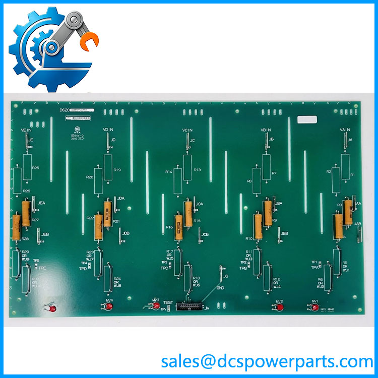
DS200NATOG2A
Related Products
These components and variants are relevant to LS2100 maintenance and replacement planning. Confirm compatibility using the applicable GE parts documentation before ordering.
- DS200NATOG1A — The G1 variation of the NATO voltage feedback scaling board. Its resistor arrangement differs from the G2 configuration, so substitution requires checking the input attenuation settings and approved assembly documentation.
- DS200NATOG3A — A G3 variation in the same voltage-feedback board family. It is a potential candidate for investigation when sourcing alternatives, but compatibility with a G2 installation must be established through OEM documentation rather than the shared NATO designation.
- DS200NATOG2ACB — A related catalog designation associated with the NATO board family. Verify the complete assembly number and revision details before treating it as equivalent to DS200NATOG2A.
- DS200FCSAG2A — A current-sensing feedback board associated with the LS2100 static starter. Its function differs from the NATO board’s voltage attenuation role; the two are not interchangeable, but may be relevant to the same equipment maintenance project.
- DS200FHVAG1A — A high-voltage gate interface board that provides SCR gate-interface and cell-voltage monitoring functions. It supports a different part of the power-conversion system and is relevant when diagnosing gate-interface or cell-monitoring faults.
- Gate Distribution and Status Board — The associated board provides gate-related functions and houses the burden resistors required for the NATO voltage-feedback circuits. Check its condition and connections when investigating feedback anomalies.
- VME Backplane — Provides the board interconnection structure identified for this assembly. Inspect the relevant connectors and backplane interfaces if replacing the NATO board does not resolve an apparent signal-path issue.
- Static Starter System — The host power-conversion and control platform. Its installed voltage levels, SCR bridge arrangement, wiring, and approved board revisions determine the correct replacement configuration.
Frequently Asked Questions (FAQ)
1. What does the GE DS200NATOG2A voltage feedback scaling board do?
The scales down voltage signals associated with the static starter’s SCR bridge so that the control system can derive voltage feedback.
Its five resistor strings cover:
- Three AC-phase voltage signals.
- Positive DC bus voltage.
- Negative DC bus voltage.
The scaled outputs travel through a 20-pin ribbon header. Correct attenuation is important because incorrect feedback can interfere with system monitoring and troubleshooting.
2. Is the compatible with the DS200NATOG1A or DS200NATOG3A?
Not automatically. These models belong to the same NATO voltage-feedback board family, but their configuration and revision details may differ.
Before selecting an alternative:
- Check the complete part number on the installed board.
- Compare the resistor, stab-connector, and jumper arrangements.
- Confirm the intended input voltage configuration.
- Verify the proposed substitution against GEI-100225 and the applicable parts list.
A board that physically fits may still produce incorrect feedback if its attenuation configuration is unsuitable.
3. Can I change the voltage input configuration on a ?
The board uses selectable stab connectors and wire jumpers to configure its resistor strings for specified voltage levels. However, these connections must follow the exact configuration documented for the application.
Do not move jumpers based on visual similarity or an assumed voltage range. Incorrect configuration can cause misleading feedback signals and potentially expose downstream circuitry to inappropriate signal levels. Isolate the equipment and follow the approved OEM procedure before inspecting or changing the configuration.
4. Does the support firmware version 3.1?
A firmware version cannot be confirmed for this board from the available identification data. The is a passive voltage-scaling circuit board rather than a standalone programmable controller.
For a system using firmware version 3.1, check the associated controller documentation for hardware-revision compatibility and any system-level requirements. Do not interpret the absence of a board-level firmware requirement as proof that every controller configuration supports it.
5. Will replacing the erase the turbine control logic?
The NATO board’s primary function is voltage attenuation, not storage of application logic. Replacing it is therefore different from replacing a controller or memory-bearing module.
Even so, the work can affect feedback signals and system operation. Before replacement, record the original board identification and jumper positions, preserve relevant controller backups, and follow the OEM inspection and recommissioning procedures. Confirm feedback readings before returning the starter to service.
6. How do I verify a new-surplus before purchase?
A new-surplus label does not independently establish authenticity or functional condition. Request:
- Photographs of the board’s identification label and complete assembly.
- Confirmation of the full part number and G2 configuration.
- Inspection records for connectors, resistor networks, corrosion, and signs of rework.
- Available functional test documentation and a clear statement of the test scope.
- Written confirmation of condition, warranty, and return terms.
For critical equipment, confirm whether the supplier has tested the board itself or has only inspected it visually.
7. What should I check before installing a replacement ?
Use this pre-installation checklist:
Procurement recommendation: For an static starter, prioritize an exact match with documented configuration and traceable inspection records. Consider another revision only after its suitability has been confirmed for the installed electrical configuration.