Description
Product Introduction (Non-Templated)
Plant engineers troubleshooting generator excitation faults inside a Mark V control enclosure face intense pressure to restore reactive power regulation quickly. When an aging power distribution or interface card throws fatal watchdog errors, sourcing an exact hardware match prevents costly downtime and extended unit outages.
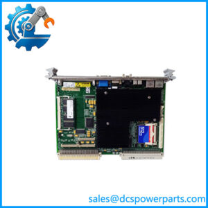
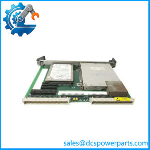
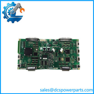
The DS200DCFBG1BLC acts as a vital control board within GE’s Mark V excitation architecture. Deploying this drop-in replacement restores stable gating and power distribution control without requiring complex cabinet wiring modifications.
Key Technical Specifications
- Board Type: Excitation Control & Power Distribution Board (DCFB)
- Compatible System Architecture: GE Mark V Speedtronic and Excitation Control Systems
- Mounting Style: Backplane or panel-mounted card assembly with secure edge locking
- Interface: Multi-pin plug-in terminal headers and ribbon cable connectors
- Operating Temperature Range: 0°C to 55°C (32°F to 131°F)
- Environmental Protection: Industrial multi-layer circuit board with protective trace routing
- Diagnostics: On-board diagnostic test points and LED status indicators
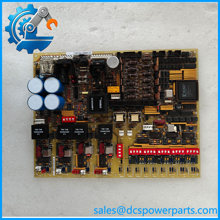
DS200DCFBG1BLC
Application Scenarios & Pain Points
Excitation system trips on large utility generators drop reactive power support instantly, risking severe grid instability and heavy financial penalties.
- Power Generation: Managing generator field current regulation and thyristor gating circuits on large steam and gas turbine skids.
- Heavy Industrial Plants: Regulating high-current DC motor drives where power supply ripple causes erratic speed control.
- Utility Substations: Controlling auxiliary exciter feedback loops exposed to harsh electrical noise environments.
A combined-cycle power facility in the Midwest experienced recurring excitation regulator faults during a high-load summer run—though your mileage may vary depending on local enclosure cooling efficiency. Swapping out the erratic interface board for a verified surplus DS200DCFBG1BLC cleared the fault registers and restored stable excitation control immediately.
Related Products
- DS200TCQAG1B: Mark V thermocouple terminal board; manages temperature monitoring loops separate from excitation power distribution cards.
- IS200EPVCH1A: Excitation control processor board; coordinates high-level generator regulation logic alongside DCFB interface modules.
- DS3800HIOC: Mark IV digital I/O board; handles turbine-specific logic conditioning rather than Mark V excitation switching.
- IS220PPRFH1B: PROFIBUS master gateway module; manages industrial network bus communications outside of exciter cabinets.
- IC086SLM082: Genius bus controller module; manages serial node networks within legacy automation environments.
The Engineer’s Guide: Field Pitfalls to Avoid
- Failing to Verify Jumper Settings: Transferring configuration jumpers incorrectly from a failed board to a replacement unit causes severe control logic conflicts upon startup. How to avoid: Always map and photograph the exact jumper and switch positions on your original board before pulling it from the rack.
- Electrostatic Discharge Vulnerability: Handling static-sensitive circuit traces without a grounded wrist strap can permanently destroy onboard logic microchips. How to avoid: Discharge your static potential against the metal enclosure backplane before touching any component pins (watch your torque on those terminal screws—overtightening strips the block threads easily).
- Ignoring Board Revision Suffixes: Swapping an older hardware revision suffix with a mismatched letter code can trigger communication blocks in the Mark V software. How to avoid: Verify that the complete catalog string, including the “G1BLC” suffix, matches your system documentation.
Frequently Asked Questions (FAQ)
- Can the DS200DCFBG1BLC be hot-swapped in a live Mark V excitation cabinet? No, standard industrial safety protocols require cutting all excitation and control power to the rack before pulling or seating modules to prevent electrical arcing and component damage.
- What causes internal component degradation on older Mark V control boards? Over extended operational lifespans, electrolytic capacitor drying, thermal stress cycling, and dust accumulation are the primary drivers of hardware failure.
- Are factory-sealed surplus units tested prior to shipment? Yes, verified surplus components undergo comprehensive bench simulation testing to validate signal continuity, voltage thresholds, and gating response speeds.
- Does this board require software configuration updates upon installation? Because it operates primarily as a hardware-level control and power distribution interface, a direct replacement generally operates seamlessly with existing system programming.
- What is the significance of the onboard diagnostic test points? They allow technicians to measure critical voltage rails and signal loops safely using a multimeter during troubleshooting phases.
- How do I prevent electrical noise from corrupting control signals on this board? Ensure that all cabinet ground straps and signal cable shields are properly secured to the reference bus bar to eliminate ground loops.