Description
Foxboro FBM228 P0922QS — Product Page
Product Overview
The Foxboro FBM228 P0922QS is a four-channel interface module that connects FOUNDATION Fieldbus H1 devices to a Foxboro distributed control system. Rather than serving as a conventional analog input or output module, it provides a communications path between the DCS and intelligent field instruments that communicate through FOUNDATION Fieldbus. Compatible devices can expose function-block parameters, engineering values, device information, and diagnostic data to control strategies and operator displays.
Each of the four H1 channels serves a separate fieldbus link. The FBM228 supports the Link Active Scheduler (LAS) function on each link, coordinating scheduled communications and supporting the operation of compatible field devices. It also supports control-in-the-field applications, where function blocks in field instruments participate in a configured control strategy. This architecture can reduce the need to route every measurement and control calculation through traditional centralized I/O, although actual control placement depends on the system design, device capabilities, and approved application configuration.
For commissioning and system integration, the Foxboro FBM228 P0922QS supports up to 64 devices per module, with a maximum of 16 devices per H1 link under the documented limits. Actual device capacity depends on bus power, cable characteristics, device consumption, repeaters, and communication loading. The specification also lists up to 128 publisher/subscriber block connections and 256 client/server block connections per module. The minimum configurable loop macrocycle is 200 ms, with the system adjusting it when necessary to preserve unscheduled communication time. These figures are planning limits, not a guarantee that every bus will support the maximum device count at every update rate.
Replacement planning requires particular care because P0922QS is an older FBM228 hardware version. Foxboro documentation distinguishes it from later RH101SF hardware, which supports newer firmware and software type 128. Legacy applications using software type 228 may specifically require P0922QS. Older P0922QS modules can participate in a redundant pair with newer RH101SF modules only when the required firmware conditions are met. Verify the installed system’s software type, module firmware, processor support, termination assembly, and redundancy adapter before purchasing a replacement.
Product Introduction — Practical Field Focus
When FOUNDATION Fieldbus devices disappear from a control strategy or a fieldbus link fails to schedule communications, the fault may involve bus power, segment wiring, device configuration, LAS assignment, firmware, or the DCS interface. The Foxboro FBM228 provides four H1 links and integrates supported field-device data into the Foxboro control environment.
Before replacing the module, document the firmware and software type, check the H1 segment power conditioner and termination hardware, and review the module’s status and channel activity indicators. After installation, validate device discovery, block communication, scheduling, and any configured control-in-the-field functions.
Key Technical Specifications
| Parameter | Specification |
|---|---|
| Module model | |
| Part number | |
| Manufacturer | Foxboro / Schneider Electric |
| Module type | FOUNDATION Fieldbus interface |
| Fieldbus channels | 4 isolated H1 links |
| Fieldbus protocol | FOUNDATION Fieldbus H1 |
| Physical-layer standard | IEC 61158 / applicable FOUNDATION Fieldbus H1 specifications |
| Link scheduling | Link Active Scheduler on each H1 link |
| Redundancy | Optional redundant module pair |
| Maximum devices | 64 per module, maximum 16 per H1 link |
| Publisher/subscriber connections | Up to 128 per module |
| Client/server connections | Up to 256 per module |
| Minimum loop macrocycle | 200 ms |
| Module power input | 24 VDC, +5%/-10% |
| Maximum power consumption | 5.0 W |
| Maximum heat dissipation | 5.0 W |
| Maximum module-to-termination cable length | 30 m |
| Operating temperature | -20°C to +70°C, subject to altitude and installation limits |
| Storage temperature | -40°C to +70°C |
| Relative humidity | 5–95%, noncondensing |
| Operating altitude | -300 to +3,000 m, subject to temperature derating |
| Vibration | 0.75 g from 5 to 500 Hz |
| Approximate module weight | 284 g |
| Module dimensions | 102 mm H × 45 mm W × 104 mm D |
| Height including mounting lugs | 114 mm |
| Mounting | Compatible baseplate on DIN rail or 19-inch rack mounting kit |
| Standard termination assembly | P0922VC |
| Redundancy adapter | P0922RK |
| Firmware/software consideration | Legacy may be required for software type 228; verify installed configuration |
Use the applicable product specification and system installation guide for final engineering limits. Fieldbus device capacity depends on electrical loading, segment design, update periods, and the configured control strategy.
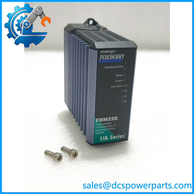
FBM228 P0922QS
Related Products
- — Later hardware version associated with newer firmware and software type 128; compatibility with legacy systems must be confirmed.
- — Earlier designation superseded by RH101SF in the applicable product family; check revision and firmware details.
- P0922RK — Redundancy adapter used in the documented configuration.
- P0922VC — Termination assembly associated with the standard arrangement.
- FBM220 — Single-channel FOUNDATION Fieldbus H1 interface for applications requiring one H1 link.
- FBM221 — Four-channel FOUNDATION Fieldbus interface from the Foxboro family; verify the exact hardware and redundancy requirements before selecting it as an alternative.
- FBM222 — Redundant-ready two-channel PROFIBUS-DP interface module; it serves a different fieldbus protocol and is not a direct replacement.
- FBM224 — Four-port serial interface module supporting compatible Modbus devices; it uses a different communications protocol.
These modules have different protocols, channel configurations, and system requirements. Select alternatives based on the actual field network and control-system architecture, not on module family alone.
Frequently Asked Questions
Q1. What does the Foxboro do?
It connects four FOUNDATION Fieldbus H1 links to the Foxboro DCS, making supported field-device function-block parameters and diagnostic information available to control strategies and operator displays. It is a communications interface, not a standard 4–20 mA analog I/O module.
Q2. Does the support redundancy?
Yes. The can be installed as part of an optional redundant module pair. The actual arrangement requires compatible hardware, baseplates, redundancy accessories, processor support, and the correct firmware configuration.
Q3. Can be replaced directly with RH101SF?
Do not assume a direct drop-in replacement. The older is associated with legacy software type 228, while RH101SF supports newer firmware using software type 128. Foxboro documentation states that mixed-version redundant pairs may be supported when the modules have the required firmware revisions. Verify the target system’s software type and firmware before ordering.
Q4. How many field devices can one support?
The published limits are up to 64 devices per module, with a maximum of 16 devices per H1 link. The practical limit can be lower depending on device power consumption, segment cable characteristics, repeaters, bus power conditioning, communication loading, and update requirements.
Q5. Which termination assembly and adapter are required?
The documented standard configuration uses the P0922VC termination assembly and P0922RK redundancy adapter. Confirm the installed hardware arrangement, termination cable, and whether the application uses a redundant pair before ordering accessories.
Q6. What should be checked if fieldbus devices are not communicating?
Check the H1 segment power supply or conditioner, bus wiring and polarity, terminators, device addresses and configuration, LAS assignment, module status LEDs, and firmware/software compatibility. Review the segment’s device count and communication schedule before attributing the fault to the itself.
Q7. Can the be replaced while the DCS is running?
The module supports redundant configurations, but that does not automatically authorize live removal in every installation. Confirm whether a healthy redundant partner is available, whether the system supports the planned maintenance procedure, and whether loss of the affected H1 links would interrupt control or monitoring. Follow the site’s approved change and maintenance process.
Q8. What should procurement verify for used or refurbished stock?
Request clear photographs of the complete module label, confirmation of the exact part number, hardware revision and firmware information where available, test scope, warranty terms, and details of included accessories. Confirm whether the unit is intended for legacy software type 228 or a compatible upgraded system. A generic “tested” claim does not prove that all four H1 links, device discovery, and redundancy functions have been validated.