Description
Emerson 7379A21G01 — Westinghouse Q-Line QAV Analog Input Card
Key Technical Specifications
| Parameter | Specification |
|---|---|
| Model | 7379A21G01 |
| Manufacturer lineage | Westinghouse / Emerson |
| Product family | Q-Line |
| Board designation | QAV |
| Product type | Analog input card |
| Number of channels | 6 individually isolated channels |
| Standard listed input range | −5 to +20 mVDC |
| Extended input range | −20 to +20 mVDC at reduced accuracy |
| Conversion method | Voltage-to-frequency |
| Digital resolution | 13-bit, including polarity bit, as listed |
| Sampling rate at 60 Hz | Approximately 4 samples/second |
| Sampling rate at 50 Hz | Approximately 3.4 samples/second |
| Common-mode rejection | Listed as 120 dB with the applicable QTB arrangement |
| Supply voltage | 12.4–13.1 VDC, reported |
| Nominal power consumption | Approximately 13 W, reported |
| Maximum power consumption | Approximately 15.7 W, reported |
| DIOB interface | 34-pin rear-edge connector, as listed |
| Field connection | 56-pin front-edge connector, as listed |
| Input accuracy | A secondary listing reports ±0.10% of upper range value; verify the applicable conditions |
| Operating temperature | Confirm from the original hardware manual; 25°C ±1°C is listed as a reference condition, not a complete operating-temperature range |
Source data comes primarily from secondary technical listings rather than a currently verified OEM datasheet. Use the applicable Westinghouse hardware manual to confirm electrical limits, accuracy conditions, and revision-specific details.
Product Introduction
The Emerson / Westinghouse 7379A21G01 is a Q-Line QAV analog input card designed for low-level signal acquisition in legacy WDPF and Ovation distributed control systems. Its six individually isolated channels use voltage-to-frequency conversion, with a microcomputer processing the measurements before transferring digital data to the DIOB. This architecture is relevant to installations that acquire small millivolt-level signals rather than conventional 4–20 mA transmitter outputs.
For maintenance teams, signal compatibility is the first concern. The listed G01 input range is −5 to +20 mVDC, with reduced accuracy reported over a wider range. The QAV card’s input configuration, line-frequency rejection, addressing, and calibration behavior must match the installed system. Before replacing the 7379A21G01, verify the card revision, field signal type, DIOB addressing, and any associated QTB hardware.
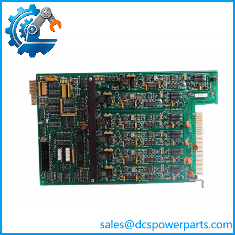
7379A21G01
Application Scenarios & Field Pitfalls — The Engineer’s Perspective
Engineering Pain Point
Low-level millivolt signals are sensitive to wiring resistance, electrical noise, grounding, and common-mode interference. A replacement card may appear functional while still producing unstable or biased readings if the field wiring, signal range, calibration, or line-frequency configuration is incorrect.
Typical Applications
- Legacy DCS analog acquisition: Collecting low-level voltage signals in compatible WDPF and Ovation installations.
- Power-generation instrumentation: Monitoring millivolt-level signals where the original control-system design specifies a compatible QAV input.
- Process measurement: Acquiring signals from compatible sensors or signal-conditioning devices with outputs within the documented input range.
- Outage maintenance and spare management: Replacing a confirmed faulty QAV card while retaining the existing Q-Line and DIOB architecture.
These are typical application categories, not confirmation of the specific instruments connected to an individual card.
Technical Pitfalls to Avoid
- Do not confuse millivolt inputs with current loops. The G01 is listed for low-level DC voltage signals. It is not a generic 4–20 mA input module.
- Respect the stated input range. The extended −20 to +20 mVDC range is reported to have reduced accuracy. Confirm the required measurement range and calibration conditions before using it.
- Check common-mode noise. The QAV architecture can use a QTB card to improve rejection of power-line-frequency interference. Verify the applicable arrangement if readings fluctuate with plant electrical loads.
- Verify line-frequency configuration. Secondary documentation describes different configuration methods across hardware levels, including jumpers or DIP switches. Check the actual board revision and approved settings rather than assuming one method applies to every card.
- Confirm DIOB addressing. Incorrect address settings can cause communication or channel-mapping problems. Record the original settings before removing the card.
- Inspect field wiring and connectors. Check the 56-pin field connection, rear-edge backplane interface, grounding, shielding, and terminal integrity against the relevant wiring drawings.
- Account for channel behavior. The six channels are described as individually isolated, but do not assume independent grounding, isolation voltage, or common-mode limits beyond those documented for the exact hardware revision.
- Validate diagnostics and calibration. The QAV family is described as using automatic zero and gain correction and reporting card-status information. Check the controller diagnostics and representative input values after replacement.
- Do not treat sampling rate as a guarantee of control-loop performance. The listed sampling rate is relatively low by modern standards. Confirm that the card’s acquisition behavior meets the actual measurement and control requirements.
- Test the complete signal path. After installation, verify representative input values, channel mapping, engineering-unit scaling, alarms, and controller response under the site’s approved maintenance procedure.
Related Products
The following models belong to the broader Q-Line QAV card family. They are comparison references, not automatically approved replacements for the G01.
- 7379A21G02 — Related QAV analog input card; confirm the supported input range and hardware revision.
- 7379A21G03 — Related QAV variant; verify signal-range and configuration differences before substitution.
- 7379A21G04 — QAV variant with a different configuration; do not assume the G01 millivolt range applies.
- 7379A21G05 — Related QAV model; confirm its input type and supported operating range.
- 7379A21G06 — Related QAV model; verify its hardware specification before considering interchangeability.
- QTB card — Associated line-frequency tracking hardware used in applicable QAV arrangements to improve normal-mode rejection.
- 7379A31G03 — QAW analog input card listed for 0–10 VDC signals; a different input-card family and not a direct substitute for the G01.
- 7379A31G04 — QAW variant listed for 0–20 mA signals; a different signal interface.
The QAV model family is documented in legacy Q-Line catalog listings. Exact input characteristics and approved replacement relationships must be established from the relevant hardware documentation.
Procurement Note
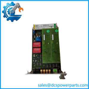
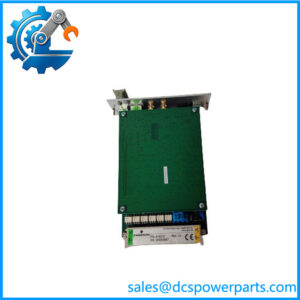
When sourcing Emerson / Westinghouse 7379A21G01, request a clear photograph of the complete board label, revision markings, connector side, and any configuration switches or jumpers. Confirm that the requirement is for the G01 low-level millivolt-input version.
Before approving a replacement, verify the input range, channel configuration, DIOB addressing, line-frequency settings, and QTB requirements against the existing system. Ask for the actual unit’s condition, inspection findings, functional-test evidence, and warranty terms. Do not infer that a card is new, unused, refurbished, or tested solely from the part number.
For a legacy QAV card, successful procurement depends on more than matching the model number: the electrical interface, revision, configuration, and field signal requirements must all agree with the installed control system.