Description
Emerson Ovation 1C31181G01 | MAU PMOD | 850nm Fiber Remote I/O Interface
Key Technical Specifications
| Parameter | Specification |
|---|---|
| Manufacturer | Emerson / Westinghouse |
| Model | 1C31181G01 |
| Product Type | MAU Personality Module (PMOD) |
| Ovation Function | Media Attachment Unit |
| Optical Wavelength | 850 nm |
| Optical Link | Up to 2 km / 6,560 ft |
| Optical Channels | 2 |
| Associated EMOD | 1C31179G01 |
| MAU Base | 1C31206G01 |
| Optical Technology | Multimode fiber |
| Application | Ovation Remote I/O network |
| Controller-Side Use | MAU |
| Power Architecture | Installed through MAU base |
The Ovation I/O Reference Manual provides the clearest technical identification. It pairs 1C31179G01 EMOD + 1C31181G01 PMOD, specifies two optical channels, 850 nm optics, and an optical link length of up to 2 km (6,560 ft).
Emerson’s spare-parts documentation separately identifies 1C31181G01 as the PMOD assembly for the Media Attachment Unit, 4-channel, 850 nm configuration. This is an important distinction: the G01 PMOD is an optical interface component, not a general-purpose analog or digital I/O card.
Product Introduction
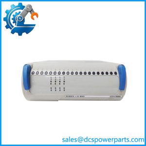
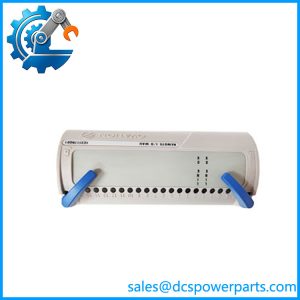
The Emerson Ovation 1C31181G01 is a Media Attachment Unit Personality Module (PMOD) used in the Ovation distributed control system’s remote I/O architecture. Its job is to provide the optical interface between the MAU electronics and the fiber link serving remote I/O equipment. The documented G01 configuration uses 850 nm optics with two channels and a nominal link capability up to 2 km.
This module should be evaluated as part of an MAU assembly rather than as an independent I/O module. The 1C31179G01 EMOD, 1C31181G01 PMOD, and appropriate MAU base form the functional hardware path. Replacing only the PMOD with a different optical variant can change the fiber architecture and compatibility.
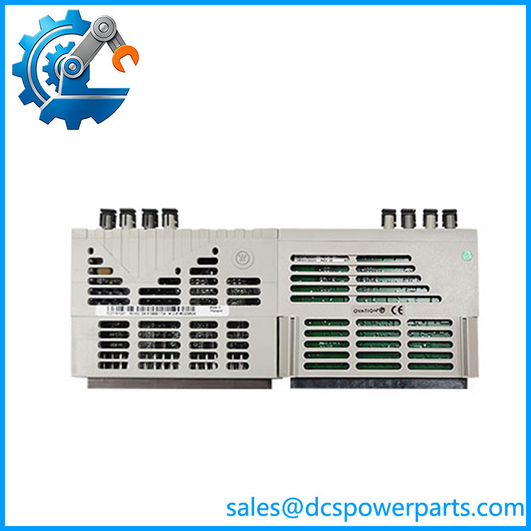
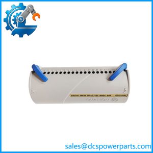
1C31181G01
Application Scenarios & Field Pitfalls — The Engineer’s Perspective
Engineering Pain Point
A remote Ovation I/O failure can look like a controller or remote-node problem when the actual fault is in the optical MAU path. A damaged PMOD, contaminated fiber connector, incorrect wavelength variant, or degraded optical link can interrupt communication with an entire remote I/O branch.
Typical Applications
- Ovation DCS remote I/O networks
- Controller-cabinet Media Attachment Units
- Fiber-connected remote I/O drops
- Power-generation control systems
- Turbine and balance-of-plant control cabinets
- Legacy Ovation I/O network maintenance
Technical Pitfalls
- Do not classify 1C31181G01 as a conventional I/O card.
Emerson’s spare-parts documentation identifies it as a PMOD assembly for the Media Attachment Unit. - G01 uses 850 nm optics.
The Ovation I/O manual specifies the G01 combination for 850 nm operation. The 1300 nm variants use different PMOD part numbers. - Do not substitute G01, G03, and G04 solely by physical appearance.
The documentation distinguishes the PMOD variants by optical wavelength, channel configuration, and link distance. - Verify the EMOD/PMOD pairing.
The documented pairing for this configuration is 1C31179G01 EMOD + 1C31181G01 PMOD. A visually compatible electronics module does not automatically establish a valid MAU configuration. - Check the actual fiber distance.
The documented G01 link class is up to 2 km. Emerson’s manual recommends keeping optical length below approximately 3.7 km to avoid requiring extended PCRR timeout settings, but the G01 hardware should still be treated according to its specified optical class. - Optical cleanliness matters.
Before condemning the PMOD, inspect the fiber connectors, patch cables, optical path, and remote-end interface. Dust or damaged fiber ends can create intermittent communication faults that resemble a hardware failure. - Verify the MAU architecture before replacing the module.
The MAU base provides the module interface and +24 V routing. The PMOD is not intended to operate as a standalone board outside its intended assembly.
Related Products
- 1C31179G01 — Ovation MAU Electronics Module (EMOD), paired with the 1C31181G01 PMOD in the documented 850 nm, two-channel configuration.
- 1C31179G02 — MAU Electronics Module associated with the four-channel MAU configuration.
- 1C31181G02 — Related MAU PMOD configuration with four optical channels at 850 nm.
- 1C31181G03 — 1300 nm PMOD variant for extended optical distance.
- 1C31181G04 — 1300 nm, four-channel PMOD configuration.
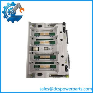
- 1C31206G01 — Media Attachment Unit base that accepts the MAU modules and provides the AUI connection and local I/O bus termination.
- 1C31203G01 — Ovation Remote Node Controller electronics used on the remote end of the I/O architecture.
- 1C31204G01 — Remote Node Controller PMOD using 850 nm fiber.
Procurement Note
For 1C31181G01, the critical identification points are PMOD, MAU, 850 nm, two optical channels, and the 1C31179G01 EMOD pairing. Do not purchase it simply as an “Ovation Remote I/O module,” because that description is too broad and can lead to selection of an unrelated I/O card.
For a replacement in an operating plant, record the PMOD part number, EMOD part number, MAU base, fiber wavelength, channel count, remote-node PMOD, and fiber-link length. The optical variant should match the installed Ovation architecture. Also inspect the optical connectors and patch cables before replacing the PMOD; otherwise a fiber-path problem can be incorrectly attributed to the module.