Description
Product Overview
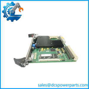
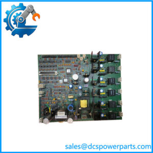
DS200DCFBG2BNC MRP420024 is one of the load-bearing cards of a GE Speedtronic Mark V cabinet, and it carries two jobs that are usually split across two boards in later architectures: it generates the control-level power that the drive electronics run on, and it conditions and measures the DC feedback that the regulator closes its loop around. GE’s card designation says so directly — DCFB, DC Feedback — and the board is routinely described in the field as the DC feedback power supply board, which is the same thing said from the other end.
The position in the system is downstream of the control power transformer and upstream of everything analogue. AC comes in from a CPT tap at 38 to 115 VAC depending on how the cabinet is configured, and the board produces +5 VDC at 4 A for logic, ±15 VDC for the operational amplifiers, and ±24 VDC for field and excitation duty, along with a dedicated motor-field supply circuit and an auxiliary driver for the cabinet’s cooling fans. That fan circuit is easy to overlook and expensive to lose: a Mark V cabinet with failed forced cooling derates itself within hours, and the board that powers the fans is the same board that supplies the logic.
The feedback half is what makes this a DCFB rather than a plain power supply. The board instruments the AC lines and the DC machine circuits — armature voltage, armature current, excitation or field current, AC line current, and the amplitude and phase sequence of the AC line — and it converts the bridge and motor voltage feedback through VCO circuits, an analogue-to-frequency conversion that keeps a low-level measurement intact inside a cabinet full of SCR switching noise. Seven DIP switches select the AC line voltage and scale the bridge and motor voltage feedback VCO circuits; twelve jumpers (JP1 through JP12 on the revisions that carry all twelve) carry the rest of the customer configuration. Both are set at the factory for a specific drive application, which is why a replacement board has to match the revision and the configuration, not merely the model code.
There is one signal on this board that ties it to the processor in a way worth knowing before troubleshooting. The /PSEN signal, routed on the 2PL connector, holds a TTL low state while the +5 VDC rail is regulating correctly and tells the drive control microprocessor to stay in its active mode; if regulation fails, the signal goes high and the processor resets. In other words, a marginal +5 rail does not announce itself as a voltage problem — it presents as a controller that will not stay up, and the fault is on the power board.
Failures on this card are legible if you know the map. Three fuses protect it: FU1, a ½ A 2AG fuse on the 115 VAC output, watched by a neon lamp LT1; and FU2 and FU3, 7 A 2AG fuses on the +5 VDC outputs, watched by LEDs CR51 and CR55. A lit LED is not a status light, it is a blown-fuse light, and that inversion catches technicians who read the panel the way they read every other board in the cabinet. Five test points — P5, DCOM, P15, N15 and ACCT — make the rails and the AC current feedback measurable without pulling the card.
The card itself is a Mark V standard-footprint assembly at roughly 0.91 kg, made in the USA, with normal (G) conformal coating, 18 plug connectors and 9 stab connectors including P1A for the positive leg of the DC bridge. It is ESD-sensitive and it retains lethal surface voltage after the primary AC is isolated — both properties are documented by GE and both are routinely violated during hurried swaps.
The suffix decodes in the usual DS200 grammar: DS200 the Mark V board series, DCFB the function, G normal coating, 2 Group 2 hardware configuration, then three revision letters — B primary functional, N secondary functional, C artwork. The BNC at the end of the user’s string is therefore B, N, C: three revision positions, not a BNC connector. That single misreading has generated some of the worst content on the internet about this board, including a claim that G1 vs G2 differ by “one or two BNC interfaces at 75 Ω”. They do not; the digit is the group, and there is no coaxial connector on a DCFB.
MRP420024 is the GE material number quoted alongside the board code in the trade, and it belongs to the ordering side of the system rather than to the hardware label. Note that the same DS200DCFBG2BNC code is also quoted against other MRP numbers — MRP433745, MRP445970, MRP56966 appear on different pages — which means the MRP reference has to be reconciled against the drive’s own bill of materials before it is treated as a unique identity. In practice a buyer should quote both strings and ask the seller to confirm the label on the physical board.
Technical Specifications
| Parameter | Value |
|---|---|
| Product model | DS200DCFBG2BNC |
| GE material number | MRP420024 |
| Manufacturer | General Electric (GE), USA |
| Product type | DC feedback and control power supply board |
| Series / platform | Speedtronic Mark V, DS200 card series |
| Suffix structure | DS200 series · DCFB function · G normal coating · Group 2 · B primary revision · N secondary revision · C artwork revision |
| Input | 38–115 VAC from the control power transformer (CPT), selected by DIP switch and CPT tap; 24 VDC nominal control bus referenced internally |
| Output rails | +5 VDC at 4 A; ±15 VDC; ±24 VDC; plus motor field supply and cabinet cooling-fan driver |
| Measurement functions | Armature voltage and current, excitation / field current, AC line current, AC line voltage amplitude and phase sequence |
| Feedback conversion | VCO (voltage-to-frequency) circuits for DC bridge and motor voltage feedback, scaled by DIP switches |
| Onboard configuration | 12 jumpers (JP1–JP12; JP13 and JP14 deleted on later revisions), 7 DIP switches |
| Test points | P5 (+5 V), DCOM (0 V common), P15 (+15 V), N15 (−15 V), ACCT (AC current feedback to the drive control card) |
| Connectors | 18 plug connectors and 9 stab connectors, including P1A (DC bridge positive leg), V1–V3, P1A/P2A, VM1A/VM1B, VB2A/VM2BA; /PSEN on the 2PL connector |
| Protection and indication | FU1 ½ A 2AG (115 VAC output) with neon LT1; FU2 and FU3 7 A 2AG (+5 V outputs) with LEDs CR51 and CR55 |
| Physical | Approx. 0.91 kg (2.0 lb), Mark V standard card footprint, normal (G) conformal coating |
| Environment and handling | 0 to +60 °C operating; cabinet-mounted in a forced-ventilated enclosure; ESD-sensitive; lethal surface voltage may remain after isolation |
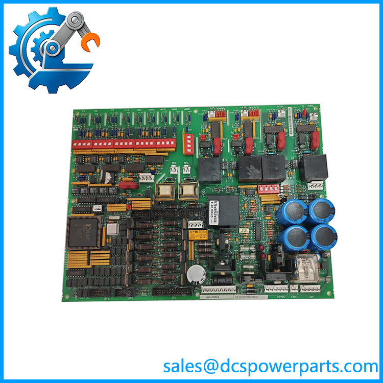
DS200DCFBG2BNC MRP420024
Key Features and Advantages
Two functions on one card, which is the point: a DCFB supplies the control-level rails and instruments the machine. In a cabinet where every slot is accounted for, that consolidation is what let Mark V keep its card count down, and it is why a single board failure can look like a processor fault, a feedback fault or a cooling problem depending on which half died first.
The /PSEN handshake, read correctly: a TTL low on the 2PL connector means the +5 VDC rail is in regulation and the drive control microprocessor is cleared to run; a high means the processor resets. For a technician, this converts an ambiguous “controller keeps rebooting” symptom into a measurement at one rail, and it explains why a power board swap so often resolves what looked like a logic fault.
VCO feedback conversion instead of straight analogue: bridge and motor voltage feedback are converted to frequency inside the board, so the signal that reaches the regulator has already survived the SCR noise environment. The scaling is set by the seven DIP switches, which is also why a board from a different drive application reads plausible but wrong values — the loop runs, the numbers lie.
Instrument-grade monitoring breadth: armature voltage and current, field or excitation current, AC line current, and AC line voltage amplitude and phase sequence. Phase sequence in particular is a commissioning-grade check that catches a phase rotation error at the CPT or a dropped leg before the drive is asked to run, and it lives on this card rather than in a separate transducer.
Fuse and lamp mapping that supports real troubleshooting: FU1 (½ A) with neon LT1 on the 115 VAC output, FU2 and FU3 (7 A) with LEDs CR51 and CR55 on the +5 VDC rails. Three fuses, three indicators, and a documented correspondence — enough to distinguish a supply fault from a load fault without a schematic in hand, if the technician remembers that a lit LED here means a blown fuse.
Configurability with a factory discipline: twelve jumpers and seven DIP switches cover line voltage, feedback scaling and customer options. The settings are established for the drive application at build time, and the field guidance is consistent — read them off the old board, photograph them, and configure the replacement identically before it goes in.
Known failure signature in the cabinet: the board drives the armature SCR gate pulse generator circuits, so a degraded supply shows up as firing asymmetry and current imbalance long before it shows up as a hard trip. That early, ambiguous phase is where most Mark V drive mysteries live.
Honest limits: this is a Mark V card. It does not belong to Mark VIe, it has no field bus, no Ethernet port, no DIN-rail housing, no IP65 enclosure and no coaxial connector. Any listing that describes those things is describing a different product with this number pasted on it.
Applications
Gas turbine control cabinets: a Mark V Speedtronic installation uses the DCFB for control-level power and for the fuel-gas valve, IGV and auxiliary drive circuits’ feedback, which is the layer where a rail sag turns into a start-up sequence that aborts without a clear cause.
Steam turbine control and generator excitation: the board carries the motor and generator excitation power supply circuits along with field current measurement, so excitation systems built on DS200 hardware depend on it for both the field supply and the regulator’s current feedback.
GE drive platforms of the same generation: DC2000, AC2000, CB2000, ME2000 and FC2000 drive cabinets use DS200 boards, and the DCFB is the power and feedback card in that family — which is how a turbine-control spare and a rolling-mill drive spare can share a part number.
Metals and heavy industry drives: DC rolling mill and coiler drives, where armature current feedback fidelity sets strip gauge, and where the ACCT test point is the fastest way to tell a feedback problem from a firing problem.
Paper machines and large pump or fan drives: multi-motor sections that need section-to-section speed consistency, running on DC drives whose regulators close on this board’s feedback and whose logic runs on its +5 rail.
Retrofit and life-extension work: plants keeping Mark V cabinets in service beyond the vendor’s mainstream support window, where the practical strategy is holding configured spares of the boards that fail most — and the DCFB, as both a power supply and a measurement front end, is one of them.
Where the number does not apply: Mark VIe cabinets and their I/O packs and terminal boards; any modern drive with a field bus interface; and any application expecting a DIN-rail power supply. Those are different products, and the market pages that conflate them are the reason this article exists.
Related Products
DS200DCFBG1B — Group 1 revision of the same DC feedback power supply board; a different hardware grouping, not a different function. DS200DCFBG1BNC — the same function in Group 1 with the B/N/C revision stack; frequently offered alongside DS200DCFBG2BNC and not interchangeable without checking the cabinet’s configuration. DS200DCFBG1BLC — Group 1 with an L-rated secondary revision; a later revision level within the same family. DS200DCPAG1ACB — the DC power supply board in the series, a distinct power card that sits in the same cabinets; do not assume it substitutes for the DCFB. DS200LDCCH1A — drive control and LAN communications board, the processor side that reads the /PSEN handshake and the ACCT feedback. DS200FGPAG1AHD — gate pulse amplifier board, driven from the DCFB’s gate pulse drive circuits; the pair that explains firing asymmetry symptoms. DS200ACNAG1ADD — ARCNET communication interface card for Mark V, part of the same cabinet’s board set. DS200IIBDG1A — IGBT board used in the drive-side assemblies, for platforms where the power stage is not SCR-based. MRP433745 / MRP445970 / MRP56966 — other GE material numbers quoted against the same board code in the trade; reconcile against the drive bill of materials rather than selecting on the MRP number alone.
Installation and Maintenance
Before installation: isolate the drive, apply lockout/tagout, and wait for the capacitor banks to discharge — the board retains lethal surface voltage after the primary AC is removed, and the neon lamp on the 115 VAC output is there precisely because that potential persists. Work grounded and on an antistatic surface; this is an ESD-sensitive card with gate pulse drive circuits on it. Read the twelve jumpers and seven DIP switches off the board being replaced and photograph them; they are set for the specific drive application, and a replacement configured to a generic default will produce plausible but wrong feedback. Confirm the revision stack on the label — Group 2, B primary, N secondary, C artwork — and the MRP number against the cabinet’s bill of materials, because DS200DCFBG2BNC MRP420024 is one configuration among several that share the DS200DCFB designation.
Installation: seat the card and verify all 18 plug connectors and 9 stab connectors, particularly P1A on the DC bridge positive leg and the 2PL connector carrying /PSEN — an incompletely mated stab connector heats and arcs under load rather than failing cleanly. Confirm CPT tap selection matches the DIP switch setting before energising. On power-up, check the three indicators in their non-fault states: LT1 out, CR51 and CR55 out. Then measure P5, P15 and N15 against DCOM, and confirm the /PSEN state transitions as the +5 rail comes into regulation.
Maintenance: treat the fuse/indicator map as the first diagnostic step, not the last — a lit CR51 or CR55 means FU2 or FU3 has opened, and the question becomes why. Replace fuses only after finding the cause; a 7 A 2AG fuse on a +5 rail does not blow from age. Keep the cabinet’s forced ventilation working, since the board drives the cooling fans and a hot cabinet shortens the electrolytic life on this card specifically. Log the revision stack and jumper/DIP configuration of every DCFB in the fleet, and hold a configured spare per cabinet type: this board sits upstream of both the logic and the firing circuits, so its failure takes the whole drive with it.
Warranty and Quality
Every DS200DCFBG2BNC MRP420024 is supplied as a GE Speedtronic Mark V DC feedback and control power supply board, identified by the full suffix stack — Group 2, B primary revision, N secondary revision, C artwork revision — and cross-checked against the GE material number 420024 before dispatch. Units are inspected for stab-connector wear and arcing, plug-connector pin condition, conformal coating integrity, electrolytic bulging, fuse and indicator condition, and any evidence of prior rework; where a Mark V bench arrangement is available the card is energised, the three rails are measured at P5, P15, N15 and DCOM, the fuse indicators are confirmed out, and the /PSEN transition is verified. A 12-month repair, replacement or refund commitment applies. Technical support covers the questions this board actually raises: decoding B/N/C as revision letters rather than a connector type, why a Group 2 card differs from Group 1, how the MRP number relates to the code, which rail to measure when a controller will not stay up, and what a lit CR51 or CR55 is telling you.
免费
今天 14:50