Description
Product Overview
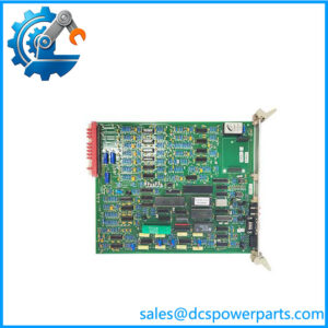
DSI1817 belongs to the same generation and the same rack as the board it is always sold beside. Its full string — DSI1817 / TRVC062335000 / CP00003934 — repeats the three-layer structure of the ALSPA P320 cabinet exactly: a board code that names the function class, an order number under which the card is procured, and a CP00… drawing number that ties it to Alstom’s documentation. That structure is the reliable part of the identification, and it is corroborated independently of any single seller: the layer semantics are stated the same way wherever the three numbers appear together, and they match the pattern of the neighbouring CMP1838 / TRVCO62345000 / CP00005202 control board.
The numbers themselves carry a second, quieter piece of evidence. Compare the two order numbers digit by digit and they sit in adjacent blocks — one in the …6233… range, the other in the …6234… range — while the two drawing numbers sit in the same CP0000xxxx register but some two hundred numbers apart. Adjacent order blocks and a shared drawing register are what a project-specific configuration looks like: these cards were numbered as a set for a particular plant’s cabinet, not drawn from a generic catalogue. That is an observation about the numbering, not a published fact, but it is the kind of corroboration a plant engineer can use when a cabinet file is incomplete.
What the board does is where the market stops agreeing, and the disagreement is worth setting out honestly rather than resolving by preference. Two sellers expand DSI as Digital Signal Input and describe a plug-in board that collects field binary signals, isolates them, filters them and hands them to the main control board over the rack bus. One seller expands it as Digital Servo Interface and describes a triple-redundant servo drive board producing ±10 V differential outputs, reading LVDT valve position feedback and closing a PID on electro-hydraulic servo valves. A third files it under a traction-control product line with a PowerPC processor and 4 GB of memory. A fourth calls it a high-frequency power controller for electrostatic precipitators. A fifth offers 16 digital inputs and 16 digital outputs with PROFINET, EtherCAT and OPC UA on a DIN rail.
Those five descriptions cannot all be right, and three of them can be dismissed on inspection. A board that lives on a euro-card rack with a DIN 41612 backplane does not mount on a 35 mm DIN rail; a cabinet card does not carry an OLED display of DC link voltage; and the “high-frequency power controller” filing is the same template error that seller applies to every Alstom number it lists, including ones from completely different product lines. That leaves the two serious candidates — input board and servo interface — and the honest position is that the public record does not settle which one it is.
What can be said with confidence is the class: DSI1817 is an I/O board of the ALSPA P320 generation, mounted in the same rack as the CMP1838 control board, in a cabinet where the field wiring passes through a marshalling layer before it reaches the acquisition electronics. Both candidate functions fit that architecture — a digital input board is the obvious companion to a control board in a turbine governor cabinet, and a servo interface board is equally plausible where electro-hydraulic valve positioning is the loop being closed. Neither candidate is contradicted by the numbering; both are contradicted by at least one of the peripheral claims attached to them.
For a buyer, this resolves into a practical instruction. The three-layer string identifies the physical card, and that is what a spare order needs. The function word behind DSI does not identify the card’s behaviour reliably enough to be used as a specification, so the replacement must be matched against the board being removed — its connectors, its front termination, its revision marking — and against the plant’s own cabinet drawing, not against a reseller’s description. A board that enumerates correctly and reports plausible values can still be the wrong board if its front-end topology differs, and no amount of seller prose substitutes for the pin-for-pin comparison.
Technical Specifications
表格
| Parameter | Value |
|---|---|
| Board code | DSI1817 |
| Equipment / order number | TRVC062335000 |
| Factory drawing number | CP00003934 |
| Manufacturer | Alstom (power automation division; control business transferred to GE, 2015) |
| Product type | Rack I/O board — digital signal input / interface class (field-documented; function word unresolved) |
| Platform | ALSPA P320 / ALSPA 320 power plant control system |
| Rack format | Euro-card plug-in, front and rear connectors, DIN 41612 backplane (platform-level) |
| Backplane supply | 5 VDC class via rack backplane (platform-level figure, not board-verified) |
| Signal isolation | Per-channel optical or galvanic isolation, supplier-stated, unverified |
| Channel count | Not published — figures quoted by sellers (8, 16, 64) are mutually exclusive |
| On-board processing | Not published — no verified processor, memory or firmware data |
| Operating environment | Cabinet interior class, approximately 0 to +55 °C (platform-level, not board-verified) |
| Ingress protection | IP20 — control cabinet installation only |
| Lifecycle status | No official end-of-life notice located; market supply is dismantled or refurbished stock |
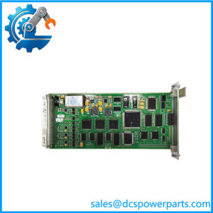
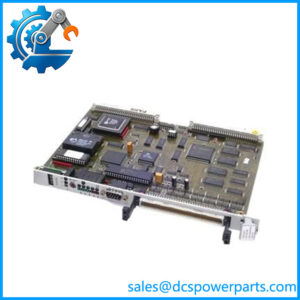
| Companion boards in the same cabinet | CMP1838 (TRVCO62345000), STO1726KO1 (4022.437.1856), CS-TX3-3.81X2.54-64TW |
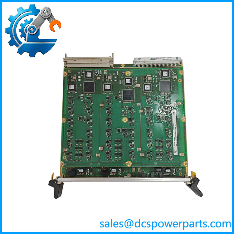
DSI1817-TRVC062335000-CP00003934
Key Features and Advantages
Three-layer identification with independent corroboration: DSI1817 names the function class, TRVC062335000 names the procured item, CP00003934 names the drawing. Unlike the board code alone, the full string can be reconciled against an Alstom or GE bill of materials, and that is the layer a plant’s own documentation is built on.
Order numbers that sit in an adjacent block to the control board’s: the …6233… and …6234… ranges, with drawing numbers from the same CP0000xxxx register, indicate a cabinet numbered as a set. When a plant has lost its as-built drawings, that relationship is often the fastest route to reconstructing which boards belong together.
Architecture that keeps the field side out of the processor side: the board sits behind the rack’s marshalling layer, so field wiring arrives on a connector rather than on the board. On a plant where loop checks are done by electricians and not by the control vendor, that separation is what makes a board swap a thirty-minute job instead of a half-day rewiring exercise.
Isolation and filtering at the channel boundary, on both candidate functions: whichever role the card actually plays, its published descriptions agree that the field interface is isolated and filtered per channel, with per-channel indication. In a turbine cabinet sharing space with contactor coils and servo power supplies, that is what keeps binary signals from being read as chatter.
Real-time rack integration: the ALSPA-generation bus is deterministic, and boards of this class exchange data with the control board on the rack’s own schedule rather than through a general-purpose network. That matters when the loop being closed is a fuel valve or an inlet guide vane rather than a slow process variable.
Honest limits, stated as limits: the function word DSI is unresolved in the public record, channel count is not published, and every detailed figure in circulation comes from a seller whose other numbers contradict it. A buyer should treat the three-layer string as identification and the seller prose as advertisement.
Applications
Turbine governor and auxiliary control cabinets: the ALSPA P320 generation appears in thermal, gas and combined-cycle unit cabinets, and DSI1817 sits in that rack as the acquisition or interface layer between field devices and the CMP1838 control board. In a governor cabinet the board’s duty is to make breaker position, valve limits, permissives and interlock contacts visible to the control loop without letting field transients into the processor.
Generator auxiliary signal collection: unit auxiliaries — pumps, fans, dampers, transformer tap positions — reach the cabinet as binary status. A board of this class concentrates those signals and passes them on the rack bus, which is how the plant’s alarm and interlock logic learns what the auxiliary plant is doing.
Electro-hydraulic valve positioning, if the servo-interface reading is correct: where the cabinet closes a loop on a fuel regulating valve, an inlet guide vane or a bypass valve through an electro-hydraulic servo, the interface board is the element that converts a control command into a valve demand and reads the position feedback back. This is the one application where the two candidate functions diverge in consequence, and it is precisely the application to confirm against the cabinet drawing before ordering a spare.
Retrofit and life-extension support: plants running ALSPA-era cabinets face a choice between full migration and staged card replacement. Staged replacement only works when a board can be identified against the plant’s drawings — the reason the TRVC062335000 and CP00003934 layers matter more in practice than the board code.
Where it does not fit: any description involving traction converters, metro propulsion, DIN-rail mounting, OLED displays, PROFINET or EtherCAT device configuration, or electrostatic precipitator RF power. Those belong to other Alstom lines and other part numbers.
Related Products
CMP1838 (TRVCO62345000 / CP00005202) — the control board of the same ALSPA P320 rack; its order number sits in the adjacent block to TRVC062335000. STO1726KO1 (4022.437.1856) — digital input/output board in the same cabinet, mated through the marshalling layer. MC1AB37 — DI/DO acquisition board referenced in the same cabinet listings; note that 4022.437.1856 is attached by one source to both this board and STO1726KO1. CS-TX3-3.81X2.54-64TW — 64-way passive signal transfer board that lands field wiring onto the acquisition boards. AOVD (N897066510E / N897066010M / N897066000A) — analog output voltage driver board of the same rack generation; the output-side counterpart to an input board. DFI-150-0003 — digital/frequency input module in the same legacy rack family, showing the functional-prefix convention that DSI follows. N895609510K (N895609010R / N895609100P) — ALSPA P320 processing assembly; listed by one source as a CPU module and by another as a 32-channel digital output board (E32OUT), a conflict that illustrates how unreliable the number layer is on this platform.
Installation and Maintenance
Before installation: settle the function question first. Compare the front termination, the connector count and the revision marking of the board being replaced against the replacement — not against a seller’s title — and confirm against the cabinet drawing whether this position is an input board or a servo interface. Record the three-layer string from the board’s own silkscreen or label, then take a photograph of the card in place with its connectors identified, because the rack position and the cable assignment are as much part of the identity as the number. De-energise the rack completely: this generation’s backplane connectors do not provide make-first-break-last grounding, so no card in this rack is hot-swappable.
Installation: work grounded, release the extractor levers evenly, and slide the board on its guides until the rear connector seats before tightening the retaining screws. Check the backplane rails at the rack before first power-up — a card that fails immediately after replacement is usually reporting a backplane or regulator fault, not its own. On power-up, confirm the board reaches a stable state and that its channel indications agree with known field conditions; a channel that reads permanently true on a de-energised field is a front-end fault, not a wiring fault.
Maintenance: keep the cabinet within its class temperature and treat cooling failure as a control-system fault. Do not re-seat cards as routine practice — every extraction wears a connector that is no longer in production. Hold one verified TRVC062335000 per cabinet, labelled with its rack position and revision, since the supply channel for this generation is dismantled and refurbished stock and matching a revision after a failure costs availability the unit does not have.
Warranty and Quality
Every CP00003934 board is supplied as an Alstom ALSPA rack I/O board and is identified against all three reference layers, with the board code, order number and drawing number reconciled to each other before dispatch. Units are inspected for front and rear connector condition, extractor lever integrity, PCB damage, rework evidence and corrosion, and for the correct revision marking; the board is checked for stable enumeration in a powered rack where a suitable fixture is available. Channel count, processor type and memory size are not asserted, because Alstom and GE never published them and the figures in circulation contradict one another. A 12-month repair, replacement or refund commitment applies. Technical support addresses what this part genuinely raises: decoding against and CP00003934, explaining why the order numbers of this board and the CMP1838 sit in adjacent blocks, and why a card that enumerates and reports plausible values can still be the wrong card if its front-end topology differs.